Continue to Site

Welcome to our site!

Electro Tech is an online community (with over 170,000 members) who enjoy talking about and building electronic circuits, projects and gadgets. To participate you need to register. Registration is free. Click here to register now.

  • Welcome to our site! Electro Tech is an online community (with over 170,000 members) who enjoy talking about and building electronic circuits, projects and gadgets. To participate you need to register. Registration is free. Click here to register now.

Monitor 5V power

Status
Not open for further replies.

2PAC Mafia

Member
Hi guys,

I want to make an easy circuit to monitor 5V. I have the feeling that sometimes DC/DC is failing at its output so I want to use a circuit which is sending a signal all time even if the problem was for a little time, until the main power is switched off. My multimeter has minimum and maximum readings but I need it and may be this is not failing until some days.

Thanks.
 
Do you want the circuit to latch when the 5V is too small. or should it indicate what is happening right now?
 
Thank you Ron. I need to monitor when 5V is going too low because DC/DC fails even if is for a short moment, then it should trigger a signal which keeps LED on (all time even if voltage is correct again) to tell me that the 5V monitored failed. I was thinking about a supervisor IC for 4,6V with a 555 as monostable for example. Something easy because I don´t have much time to spend on it due to too much work but I want to use it as a tool in some units which I suspect that could be the problem, intermittent failure.
 
Thank you Ron. I need to monitor when 5V is going too low because DC/DC fails even if is for a short moment, then it should trigger a signal which keeps LED on (all time even if voltage is correct again) to tell me that the 5V monitored failed. I was thinking about a supervisor IC for 4,6V with a 555 as monostable for example. Something easy because I don´t have much time to spend on it due to too much work but I want to use it as a tool in some units which I suspect that could be the problem, intermittent failure.

A 555 timer has quite a few extra components and connections for something like that. Consider using a latch, flip-flop, or comparator instead:
https://www.digikey.ca/product-detail/en/texas-instruments/SN74LVC1G373DBVR/296-18588-1-ND/857357
 
Last edited:
Thank you Ron. I need to monitor when 5V is going too low because DC/DC fails even if is for a short moment, then it should trigger a signal which keeps LED on (all time even if voltage is correct again) to tell me that the 5V monitored failed. I was thinking about a supervisor IC for 4,6V with a 555 as monostable for example. Something easy because I don´t have much time to spend on it due to too much work but I want to use it as a tool in some units which I suspect that could be the problem, intermittent failure.
I'd use a diode on the output of the power supply, and a large capacitor on the circuit's side. That way, if the power fails, the cap will discharge while trying to keep your circuit on, and the diode will prevent that charge from going back into the power supply.
 
One of these comparator latches should work in conjunction with a supervisor IC. A rail-to-rail output op-amp would work too in a pinch.

The MOSFET version is more difficult to mess up. The diode version requires that the Out-of-rest threshold be set high enough that the diode is forward biased before the out-of-reset threshold is reached when the input is going from LO to HI. Otherwise, the circuit is unable to establish the diode's role in allowing the output to pull (and maintain) the non-inverting input LO before the input rises high enough to cause the output to trigger a state change.
 

Attachments

  • Brownout Comparator Latch.PNG
    Brownout Comparator Latch.PNG
    182.5 KB · Views: 142
Last edited:
You are watching the 5V.
Does this "watch voltage circuit" need to live on the 5V or is there another source of power?
How long is the 5V "low"? Does the 5V go all the way down to 0 volts. How long is the 5V bad?
 
How tight is the detection window? Do you wanr to detect a small deviation such as dipping below 4.75 V, or something larger such as a 2.5 V or 3.0 V threshold level? IOW, when the supply bounces, how big a bounce is it?

ak
 
Hi guys,

the thing is not so accurate, as soon the 5V monitored goes 0,5V down the monitor circuit should detect it. The power of the circuit can be different from the power monitored. As an example I did this quick design but it´s not working, I get only 6V at relay... Zener is 4,6V so if the 5V coming from DC/DC connected to non inverting input goes below 4,6V then output of LM2903 should go to ground, isn´t it?

Thanks everybody.
 

Attachments

  • 20180315_113458_resized.jpg
    20180315_113458_resized.jpg
    276.2 KB · Views: 108
May be the best is to buy another cheap multimeter with MAX MIN values... :)

I´ve seen one for 50€.
 
As an example I did this quick design but it´s not working, I get only 6V at relay... Zener is 4,6V so if the 5V coming from DC/DC connected to non inverting input goes below 4,6V then output of LM2903 should go to ground, isn´t it?
Depends on the resistance of the relay coil, or whatever is connected to the comparator output.

Datasheet + load resistance + Ohm's Law = ???

ak
 
but it´s not working,
I don't know what "M" is. I revered M and relay contacts.
When the relay is turned on it will stay on as long as 12V is alive. (add red line from coil to contacts)
You might need to put a large cap across the Zener diode so the voltage on (-) comes up slow. (there might be a power up problem)
upload_2018-3-15_8-7-12.png

edited--- put a diode across the relay coil. pointing up ---edited
 
M is a motor of a fan with a mark on it. If comparator sends ground on the output switches relay on and this switches on the fan, position of fan changes (mark is not in the same position) so I know voltage failed.

OK, that´s a good idea about sending signal of switch of relay to ground to keep relay on, so the motor can be replaced by a light and it stays on. Now my doubt is about why comparator is not sending a pure ground so it´s not activated. Relay is 70 ohm.
 
The circuit in post #9 should work as a detector, but will not latch without one more component. First, disconnect the load and replace it with an LED and resistor to verify that the detector trips at the correct input voltage. A 3.3K resistor will set the LED current to approx. 3 mA.
Relay is 70 ohm.
A 70 ohm load at 12 V is 171 mA, WAY more than a typical comparator can handle by about 10x. Even momentary operation at this current can damage, or at least weaken the comparator output stage. Test the circuit with a low-current LED as above.

ak
 
With the LED works fine as you said. May be I can use some driver as ULN2003 to do the same driving a relay.
 
A single bipolar such as a 2N4401 or MOSFET like a 2N7000 will handle it.
Diode across relay coil.
Resistor in series with base. None needed for the gate.

Note: a driver transistor will invert the logic polarity. Swap the comparator inputs to correct.

Once that is working, adding one diode and one resistor will make it latch.

ak
 
Hello,

on Monday I´ll try to test this (attachment), I think this is the theory about what we have been speaking about.
 

Attachments

  • 20180316_221554_resized.jpg
    20180316_221554_resized.jpg
    187.7 KB · Views: 89
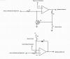
The schematic is OK as far as it goes, but it could use two things.

First, a noise filter on the 5 V input so the relay doesn't try to respond to millisecond noise transients.

Second, some hysteresis. This is a little positive feedback around the comparator to immunize against noise in a different way. A comparator is a linear amplifier running "wide open", so its output is intentionally saturated against either the high or low voltage rail. but if the two inputs are almost exactly equal, like 1 microvolt apart -- which they will be as the 5 V input transitions across the reference voltage -- the comparator will amplify this by 1 million (or whatever its open loop gain is) and the output will be a volt or two instead of saturated. Whatever noise is on the input will be amplified, and the output will be a noise burst that can drive downstream circuits crazy. The solution is a large value resistor from the output to the + input. Start with 100K in your case. Now when the first noise tip causes the output to start to transition, the positive feedback shifts the reference voltage. If the input moves downward 1 uV to cause the output to change, it now must move up around 50 mV to cause the output to change back. The circuit now has 50 mV or "noise immunity". I'm winging rough estimate numbers here, but that's the idea.

In post #1 you said you wanted the circuit to latch once there was a brief 5V dip. To do that, replace the 100K hysteresis resistor with a diode. Now the reference will shift from approx 4.5 V to around 9 V, something the input never can overcome. The output will stay high until the circuit is reset. You can add a reset button as a dead short across the 10K pot.

To make sure the circuit powers up in the non-reset mode, add a 10 uF capacitor across the pot so the reference voltage comes up to its threshold value later than the input.

ak
 
Status
Not open for further replies.

Latest threads

New Articles From Microcontroller Tips

Back
Top