Continue to Site

Welcome to our site!

Electro Tech is an online community (with over 170,000 members) who enjoy talking about and building electronic circuits, projects and gadgets. To participate you need to register. Registration is free. Click here to register now.

  • Welcome to our site! Electro Tech is an online community (with over 170,000 members) who enjoy talking about and building electronic circuits, projects and gadgets. To participate you need to register. Registration is free. Click here to register now.

Momentary relay?!

Status
Not open for further replies.

deanwarez

New Member
Hi people, im not really sure what the proper jargon is for what im trying to achieve - so the title may not be what im after... ill explain the appliance...

its for my car. i have a motorised touch screen lcd that has a constant +12v and then a ground to the car battery. i have taken apart the monitor and soldered on wires to the "eject/open" switch (the switch when pressed folds out the screen). so i have these wires coming out of the back. now i need the circuit.

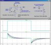
now the theory of the circuit... utilising the +12v ignition cable that gets powered when the ignition is turned. as you guessed it... i want a relay to charge when the ignition is powered - thus connecting the monitor switch wires.

--> IGNITION WIRE +12 LIVE
--> ACTIVATE RELAY
--> WAIT A SPLIT SECOND (emulating the press time)
--> DEACTIVATE RELAY

--> IGNITION WIRE +12 KILL
--> ACTIVATE RELAY
--> WAIT A SPLIT SECOND (emulating the press time)
--> DEACTIVATE RELAY

anyone care to shed some light and help on this circuit. im fine at building circuits but designing them im poor.

thanks

x
 
Are there two different "buttons" to push momentarily or only one, which toggles (opens/closes) the screen?

Assuming only one button, the attached simulation might work for you. I show only the relay coil. I assume you will wire the normally open contacts to your push button.

I assumed some things about your car, including that the ignition switch has at least 1A flowing through it when it is on.

The design is based on finding a 12V relay that has a coil resistance ≥ 200Ω. It should also be non-polarized. There are some relays out there that biased with a permanent magnet, so they pull-in with current flowing only one way. For this circuit to work, the relay must pull-in with the current flowing in either direction.

The timing capacitor is a large polarized electrolytic. I ran the sim with four different values of the cap: 250uF, 500uF, 750uF and 1000uF. Note the duration that the current flows. The relay will stay pulled-in until the current drops to about 1/3 of its initial value.
 

Attachments

  • MomRelay.jpg
    MomRelay.jpg
    187 KB · Views: 379
Last edited:
yes there is only one momentary push button on the screen. so your schematic should work. :) . im having problems understanding your circuit though lol. :-S um... any chance of quick re-draw any easier way? lol. sorry mate. x
 
Last edited:
Everything on the left side of the circuit diagram is already in your car. The two components on the right side are all you have to add, just a relay, and a capacitor.

Read the previous post again, and notice that just not any 12V relay will work. You will have to go looking for one that has a higher coil resistance compared to "automotive" relays such as made by Bosch.

The capacitor value controls the duration of how long the relay is pulled in, the bigger, the longer...

Basically, the current through the relay pulls it in as the capacitor charges when you turn on the ignition switch. When you turn the switch off, the relay discharges the capacitor backwards into the car. The current pulse/duration through the relay coil is similar in both directions, except for the direction.
 
Last edited:
Don't depend on having +12V while starting your car. The battery output voltage can drop by as much as half while the starter is engaged.
 
True... but before the starter turns the car turns on the accessory... so at the time of this relay powering the voltage SHOULD be 12v. then when the car turns over all the relay work would have been done. x
 
So, what happend when the relay de-energized while the starter motor is engaged, then re-energized after the car is started?
 
Maybe you'll get lucky, and the cap will be half-charged while starting, then the relay won't engage when DCV returns to 12V.
 
Hmm... when the cars actually running the alternator makes the voltage about 14v... so would there be a way to put in a threshold of 13v until the relay is charged. would that solve the issue? x
 
I love the scheme for it's simplicity, but there are variables. For example, on trun-off, will the "other" loads be enough to discarage the cap rapidly enough to engage the relay? IMHO, a workable solution will be more complex.
 
yeh thats what i thought. i personally thought up of two independant circuits controlling when the voltage is ON and when the voltage is OFF to charge the relay - with the use of a few diodes to isolate the seperate circuits x
 
Take a look at how to configure a 555 timer as a one-shot (monostable) It might even be in one of the tutorials, I haven't looked. Run it at 5V so you get consistant voltage. You'll need a simple regulator to do that. Generate a pulse whenever battery voltage crosses 13V. Use an active full-wave rectifier between the pulse and the 555 timer input. The way, you can get a properly oriented pulse to trigger the one-shot. You'll have to search for the rectifier circuit, for some reason I can't find anything I need on the web anymore. But it is made from an op-amp and a couple diodes. The one-shot can drive a relay, or might just drive the input to your device directly.

Hope this makes sense. If you need a drawing, I can make a basic one at a later time. Don't have access to my graphics pkg right now.

My solution is much more complicated, I know. It's up to you what you want to do.
 
Last edited:
I added the starter motor and the drop in battery voltage during starting. I assumed that during starting, the battery voltage drops to 9V as modeled by the battery series resistance and the starting current of about 250A.

I think that the current pulses caused by the starter on and starter off events are not large enough to pull in the relay.

As for the timing capacitor discharging though the car's load when the IGN key is turned off, I already considered that. Show me a car where the current through the Ign switch is not at least 1A.
 

Attachments

  • MomRelay.jpg
    MomRelay.jpg
    271.6 KB · Views: 203
Show me a car where the current through the Ign switch is not at least 1A.

Couldn't reisist :D

Ok I know, I have to I need something productive to do!
 

Attachments

  • peddleCar.jpg
    peddleCar.jpg
    93.1 KB · Views: 160
ok. so the original circuit should work :) . now its just finding a relay thats suitable. also i cant see the relay is activated when the ignition 12v feed is 0v though - i know my skills arent good. but fancy just explaining briefly how? :eek: 
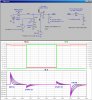
. if a relay states nothing about the polarization - can i assume that its a non-polarized, or is standard polarized? and if i found a relay with a higher resistance would the capacitor value need changing? cos i couldnt find one with a 200Ohm coil resistance and 12Vdc coil voltage. x
 
Look at the current through the relay plot. Note that when the IGN switch is turned off, the capacitor was previously charged to 12V, and then it discharges through the relay into the 12 Ohm load resistor, which is all the stuff in the car that the IGN switch normally powers. We are banking on the fact that the loads add up to at least an Amp.

You can go as high as you like with the relay coil resistance; the higher the resistance, the smaller C1 can be.

You can go lower, but C1 becomes very big.
 
Last edited:
ok thats starting to make sense. and just one more question to help me understand... how does the capacitor or coil resistance stop the relay from being constantly powered when the ignition 12v is on? x
 
Status
Not open for further replies.

Latest threads

New Articles From Microcontroller Tips

Back
Top