Continue to Site

Welcome to our site!

Electro Tech is an online community (with over 170,000 members) who enjoy talking about and building electronic circuits, projects and gadgets. To participate you need to register. Registration is free. Click here to register now.

  • Welcome to our site! Electro Tech is an online community (with over 170,000 members) who enjoy talking about and building electronic circuits, projects and gadgets. To participate you need to register. Registration is free. Click here to register now.

Model train Signal automation

Status
Not open for further replies.

Shelton

New Member
Hi All

I have a question.

What I am trying to achieve is this:

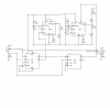
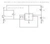
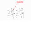
I have a model train signal that has a LED which can change between red and green.
What I want to do is change the signal manually with a switch from the default position of Red to Green. Once the train goes past the signal, the signal changes to Red automatically and stays at Red until I manually change it to green.

Does anyone know of a circuit on how to do this? Would I need a relay or something else ? Is there a schematic out there or has someone done this previously? I have looked at the home.cogeco.ca/~rpaisley4/CircuitIndex.html website but could not find anything that has a manual change from Red to Green and a automatic back to Red.

Cheers
Shelton.
 
What type of sensor detects that a train has passed?


Seems like you would want to automate this a little further, and have the train stop automatically (not pass) if the signal is red. ;)
 
just use a change over switch, biased one way. so normal position is red, and you switch it to green, when released it goes red again.

https://uk.rs-online.com/web/search/searchBrowseAction.html?method=getProduct&R=0320950


for more fun though, reed switches in the track, magnet under the loco, a few more relays and an automatic system

way back my Dad and I built a 4 aspect system based on this. had more relays than a real signal box ;) now a pic would probably do the whole thing, without all the clicking, but where is the fun in that?
 
Last edited:
Hi All

Well to begin with I want to keep things simple. All i want is the signal to change to Red after the train goes over a certain section. I was thinking of using a Infrared detector or something.

Are there any schematics that can do this ?

Cheers
Shelton.
 
Sounds like you need a train detection circuit plus a S-R (or J-K) flip flop. The site that you named has various detection circuits. The flip flop is set by a signal from the detection circuit and reset by a momentarily closed switch. The red and green leds are connected to the outputs of the flip flop.

**broken link removed**)
 
Here is a circuit i was playing with

train passes over section of track, yellow led comes on then two alternating flashing leds come on.
all stays on until train has pasted crossing
has yet to be actually built, just simulated on LT Spice
uses photo transistors
 

Attachments

  • trainX.PNG
    trainX.PNG
    26.9 KB · Views: 824
You can use a relay to latch the LED on and to control the LEDs.

Attached pdf shows how you could do it with a SPDT relay for separately driven LEDs or using a DPDT relay for a bicolour LED. Train detect switch can be a reed switch or just a wire to touch an appropriate part of the train as it passes.
 

Attachments

  • Schematic Pr.pdf
    30.3 KB · Views: 411
Hi All

I don't need any flashing lights - I am in Australia and our signals are way different to those in the USA.

Dougy I will take a closer look at your schematic - looks like what I was needing but is using the relay the way to go ?

Cheers
Shelton.
 
Dougy I will take a closer look at your schematic - looks like what I was needing but is using the relay the way to go ?
Obviously it's up to you. You can do the same thing with a couple of transistors wired as an RS F/F. Or with a couple of AND or NAND gates (and support RC components). As always there's many ways to do garner the same outcome.
 
Also, I need to use only one LED which has Red and Green - not two as drawn on the schematic - also will Dougy's schematic work on 12v DC ?
 
Dougys circuit dosn't work as you want

Red stays on all the time except when pressing the N/O pushbutton. Release the button, Red comes back on
In attached schematic the LEDs come on automatically. You need two sensors or one sensor and one monetary push button.
yes the schematic I have posted will work on 12v but resistors will need a higher value.
R = Voltage (12) divided by current (20ma)
BUT the forward voltage of LED needs to be included.
LED Resistor Calculator
time to do some caculating
 

Attachments

  • train flasher1.PNG
    train flasher1.PNG
    22.1 KB · Views: 694
  • wrong flasher.PNG
    wrong flasher.PNG
    28.1 KB · Views: 618
Sheltons signal controler

Dear Shelton,

Seems that you need to give the guys a bit more info abou your LED. Bi-color LEDs come in two varieties. They come as two leds with a common cathode (power negative) lead and two extra leads for the two anodes. This three lead version would be easier to deal with for your project. Then there is the two lead version which has two LEDs in one package wired in parallel and back to back. when current passes in one direction an LED lights up. Pass the current in the oposite direction the other lights up.

Either way the best way to solve your problem is via a latching relay. Install a magnet under your engine(s) and a magnetic reed switch in the middle of your track (you figure that out) the reed switch momentarily applies voltage to the relay coil. All the relay contacts (there should be at least two sets) close. However one set of normally open contacts is wired in parallel with the reed switch. As the engine passes over the reed switch it will naturally open but current will still be applied to the relay coil via the relay's own "latching" contacts. This condition will be maintained until the rlay operating voltage is momentarily removed. This can be done by a normally closed push button switch.

I suggest that you get a 24 volt "Potter Brumfield" relay. They work quite well at 18 volts. A 12 volt relay would work too but if you ar using a rectified output from your throttle a resistor in series with the relay would be needed to drop the voltage a bit.

As I'm new here I don't know how to attach drawings yet but my e-mail address is plowry10@hotmail.com. I'll forward some diagrams if you wish using normal E-mail protocol. In the mean time give me the exsact info pertaining to the type of LED you are dealing with.

Good luck

RP

Pete
 
Sheltons signal control

The relay latching circuit is fine except the "green on" push button should be a "normaly ON" type. (When pushed it opens the contacts momentarily)
 
Shelton's signal control.

Shelton.
Two things. VCC is the nomer used for indicating the power source for driving the circuit. It can be positive or negative depending on the type of devices you are using (NPN or PNP transistors for example).

As for your LEDs being in one housing, well the latching circuit given you contains two options. One for the three lead LED where two elements are just connected together internally, the other for the two lead parallel "back to back" type. Good luck
 
here is a circuit that does it all automatically No relays etc. and yes it is a working project and a pc board is available
**broken link removed**
 
There are several methods of detection, much depends on your control system. The least intrusive involves using photo-cels and ambient light. The most difficult part is the logic to display aspects appropriate to the situation.

If links are permitted, look at **broken link removed** That will drop into my website at the correct page. If you think the equipment there will solve your problem, email me. The fundamental circuits are not proprietary, and I'm always ready to assist a novice.

Some documentation is posted there, also a PDF with installation procedures for my boards. The instructions will contain much insight into signal systems as systems.

Artificer (bhudson@hudsontelcom.com)
 
Status
Not open for further replies.

Latest threads

New Articles From Microcontroller Tips

Back
Top