Continue to Site

Welcome to our site!

Electro Tech is an online community (with over 170,000 members) who enjoy talking about and building electronic circuits, projects and gadgets. To participate you need to register. Registration is free. Click here to register now.

  • Welcome to our site! Electro Tech is an online community (with over 170,000 members) who enjoy talking about and building electronic circuits, projects and gadgets. To participate you need to register. Registration is free. Click here to register now.

Model Rocket Launcher

Status
Not open for further replies.

jholguin

New Member
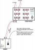
Me and my son build estes model rockets and would like to launch these by remote control. After doing some research on electronic ignition devices at the hobby shop I found that an electric ignitor requires about 1 amp to fire. I'd like to build a firing module with 12 outputs that we can fire these ignitors with by pushing one button remotely. I'm not looking for a wireless system. I feel more comfortable using a wired system. I'm not really thinking of a box with 12 buttons for each ignitor. Here's what I envision:

I'd like to have a small hand held box with one button. Two wires from this box go to the firing module about 100ft away. The firing module will have the 12 outputs. When the button on the hand held box is pushed, a pulse is sent to the firing module and output 1 fires. When the button is pressed a second time, output 2 fires. A third time, output 3 fires. It would like a manual sequential firing, until all outputs are used. I'm not too sure how to accomplish this electronically. Anyones help would be appreciated.
 

Attachments

  • Firing-Diagram.jpg
    Firing-Diagram.jpg
    88.8 KB · Views: 3,499
Last edited:
If you want to have an easy time use 10 outputs a 4017 decade counter could do the job. It can be done with 12 but it is trickier. The thing I am wondering about is a signal traveling 100ft, shouldn't be a problem though...
 
I would consider a 12 position rotary switch. That adds an element of safety, in that the knob MUST be manually turned to the correct rocket before it can be fired. Also you should check with the safety regulations of your rocket club to make sure the ignitor complies with the regulations.
 
I could use a rotary switch. But that would require multi-conductor cable to be run to the firing module. That cable is pricey. Or am I missing something? I'm kinda looking for ideas and any schematics would help.

I'd have to look into the decade counter idea. I just got an email from a friend and he mentioned a solid state relay board. But not sure how that works yet. I really want to send a low voltage signal from my hand held and have the firing module produce the full 1 amp.
 
Hi jholguin,

I understand you want to launch up to 12 rockets either manually or automatically ripple fired.

Each rocket requires its own launch circuit - otherwise if you want to save on cable connect them all parallel and have them take off simultaneously. :D

With a decimal counter (up to 10, meaning actually 9, since zero is already active on null count) you'll have two options to launch rockets:

One by one by pressing a button or ripple fire by determining the end of count between 2 and 9. End of count might be set with a rotary switch.

Do not forget to add a safety circuit by either using two pushbuttons connected in series or preferrably an extra arm/disarm switch secured by a key.

As an additional safety precaution connect the igniter battery just shortly before you intend to launch.

Boncuk
 
I would consider a 12 position rotary switch. That adds an element of safety, in that the knob MUST be manually turned to the correct rocket before it can be fired. Also you should check with the safety regulations of your rocket club to make sure the ignitor complies with the regulations.

:O Thats 13 wires @ 100 feet!
 
Yup, drew it myself. But have to move from paper to real hardware!
What do you guys think about a solid state relay?
 
Hi jholguin,

you can save on cable using one battery terminal to be connected to all ignitors and interrupt the other with individual switches. Using a 6X2 shielded cable use the shielding for ground and the twelf wires for "hot switching".

I think SSRs are too expensive. I suggest using MosFet transistors.

You require relatively little power to supply the ignitors (max. 6V/1A). For 100feet cable use 0.8square mm wire cross section.

Using a decimal counter stepping to the next rocket normally would touch it off right away. Stepping up without firing requires a more complex circuit.

Boncuk
 
A way to cheat would be to use Cat 5 or similar computer network cable. Its dirt cheap if you know where they are reworking a school or office building! Dumpster diver cheap. ;)

Basically that would give you 8 lines capable of firing 7 igniter's at well over 100 feet with a 12 volt source. If you did a little electrical slight of hand with 14 diodes you can effectively set it up so that if one polarity is used 7 can be fired and then when you switch your line polarity over the other 7 can be fired.

What you would do is set up 7 igniter's with diodes facing one way. Then seven more with the diodes facing the other way off of those same lines. That way the signal that sets off an igniter only works with its corresponding line polarity.

Using 7 push buttons and a DPDT switch to reverse your battery supply voltage plus the 14 diodes you would get a rather simple but effective remote launch system capable of handling up to 14 individual launch signals.:)
 
I was going to suggest cat5 cable. Multiplexer/demultiplexer and power source near the rockets.
That sounds like a nice system. 8 Wires make for 128 possible outputs.

I would possibly go for 4wires for 15 firing inputs (and an inactive code), A pair for return, and a pair for safety purpose. The firing system would ony be active if the pattern on this pair is the one intended (one high, one low for example. Needless to say, I would add ample capacitor delays on such a system, so that firing is not triggered when rockets are being installed.
 
schematic finally

See below. A friend of mine helped me with this. The blue pieces I'm not understanding completely yet. Mosfets and maybe a gate? I need some feedback and possibly any improvements. I still need to add a continuity check on the slat.
 

Attachments

  • Three-Wire-System.jpg
    Three-Wire-System.jpg
    85.3 KB · Views: 1,249
to check continuity use a 100Ω resistor in the common igniter supply to be shorted for active firing. With a 100Ω resistor the current flow is not high enough to ignite. Then measure the voltage drop across each individual igniter.

Use the voltage drop across the igniter to input into a comparator circuit.

E.g. battery voltage = 6V, igniter resistance 3Ω should cause a voltage drop of 175mV with the 100Ω series resistor. Setting the reference voltage to 100mV you get a definite continuity indication.

Here is a circuit suggestion. The test is valid only if the corresponding counter output is active. Using OpAmps with a strobe input the indication is always valid when the OpAmp is strobed.

Instead of using a 74HC08 (AND-gate) to cascade counters you might use a 4081 CMOS AND-gate. That way you might omit the 5V regulator.

I further suggest to use the fire button as per your cuicuit only for ripple firing. For single fire add a second button directly to the clock input (pin14) of the first conter putting a diode (1N4148) between pin3 (NE555, U2) and pin2 (74HC08). Pull pin 2 to ground using a 4.7KΩ resistor for the 74HC08 and use 10K for a 4081.

Boncuk
 

Attachments

  • CONTINUITY.gif
    CONTINUITY.gif
    9.9 KB · Views: 896
Greetings jholguin

In the interest of safety, one thing you may wish to consider is that MOSFETs very often fail short circuit. It may be worth including LEDs to monitor each firing circuit for voltage to avert an unintended ignition at the launch pad. I myself have be flying model rockets for 20+ years and witnessed a launch pad accident involving serious burns.
_______
trident
 
Details

Instead of using a 74HC08 (AND-gate) to cascade counters you might use a 4081 CMOS AND-gate. That way you might omit the 5V regulator.

I further suggest to use the fire button as per your cuicuit only for ripple firing. For single fire add a second button directly to the clock input (pin14) of the first conter putting a diode (1N4148) between pin3 (NE555, U2) and pin2 (74HC08). Pull pin 2 to ground using a 4.7KΩ resistor for the 74HC08 and use 10K for a 4081.

Boncuk, your killing me. :confused: 
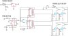
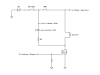
I looked at your diagram and couldn't follow. Maybe it was just too late at night. Can you help by drawing in more of my schematic modified into your suggestions?

trident9 Greetings jholguin

In the interest of safety, one thing you may wish to consider is that MOSFETs very often fail short circuit. It may be worth including LEDs to monitor each firing circuit for voltage to avert an unintended ignition at the launch pad. I myself have be flying model rockets for 20+ years and witnessed a launch pad accident involving serious burns.

Trident, can you expand a little on this suggestion. Do you mean continuity?
 
Greetings jholguin
This is an example of one way to check if any of the channels have power, ie a shorted MOSFET, with an LED or better still use a low current buzzer.
_______
trident
 

Attachments

  • Launcher.png
    Launcher.png
    3.2 KB · Views: 652
Greetings jholguin
This is an example of one way to check if any of the channels have power, ie a shorted MOSFET, with an LED or better still use a low current buzzer.
_______
trident

Hi trident9,

I guess the rockets will fire without continuity test. The circuit needs the "ARM" switch to be closed for current flow across the igniter.

A better way is paralleling a current limiting resistor with the arm switch (~100Ω) for the continuity test. To arm the circuit the resistor just has to be shorted by the switch.

So the switch has dual functions: TEST/ARM.

Here is a simple test circuit. The equivalent counter output must be known using one LED. Connecting one LED in series with the igniter the respective LED will light when the transistor is conducting.

Regards

Boncuk
 

Attachments

  • IGN-CONT.gif
    IGN-CONT.gif
    8.8 KB · Views: 625
Last edited:
Hi jholguin,

in the meanwhile I worked out a circuit design with following features:

- manual or automatic (ripple fire) launch
- variable ripple speed from 0.5 to 5Hz
- LED controls for the rockets being fired and sequenced for continuity test
(32 LEDs total)
- continuity test either manually sequenced or automatic.
- manual firing only possible by pushing two buttons. (in case the ARM switch is activated and somebody pushes a button inadvertantly)
- ripple firing can be interrupted by disabling the timer circuit.
- debounce circuitry for the manua FIRE buttons

Continuity test is only valid for the nominal igniter resistance. Either interruptions or shorts are indicated as NO-GO by leaving one of a pair of LEDs unlit. The continuity test uses strobed comparators (LM311) for 100% reliability.

Board: Double sided, dimensions 6.65X6.915inches.

Regards

Boncuk
 

Attachments

  • ROCKET-LAUNCHER.gif
    ROCKET-LAUNCHER.gif
    42.9 KB · Views: 830
Status
Not open for further replies.

Latest threads

New Articles From Microcontroller Tips

Back
Top