Continue to Site

Welcome to our site!

Electro Tech is an online community (with over 170,000 members) who enjoy talking about and building electronic circuits, projects and gadgets. To participate you need to register. Registration is free. Click here to register now.

  • Welcome to our site! Electro Tech is an online community (with over 170,000 members) who enjoy talking about and building electronic circuits, projects and gadgets. To participate you need to register. Registration is free. Click here to register now.

Ml2010 mini-lab connected to a osilloscope

Status
Not open for further replies.

DJ380

New Member
I have a knight ml2010 mini-lab and a Tektronix tbs 1104 oscilloscope, I am a student at Devry for my bachelor's in electronic technology and I am doing a lab and the time setting on the lab sheet got me confused because when I set the time on the scope the waveform I have set goes almost out the screen can anyone give me some pointers so I can finish this lab
 
What time base have you set?
Where is the horizontal trigger set? ( small arrow on the top of the display )

I have a lesser scope, but some time bases do not have a horizontal trigger, but these are 100ms -
 
One of the time base sets is 50ns/div, 0.5ms/div and 200ns/div so I move the arrow at the top of the screen and not the horizontal on the bottom
 
There are two triggers... It sounds like your wave is partially off screen... Are you new to oscilloscopes??

What frequency ( ish ) are you trying to watch... Can you post a copy of the lab question so we can help you select the correct settings..
 
a. Set Channel 1 of oscilloscope to 2VDC/division.

b. Set time-base of oscilloscope to 50μsec/division.

c. Set oscilloscope triggering to positive edge for Channel 1.

d. Set coupling of oscilloscope to DC.

e. Connect oscilloscope probe from oscilloscope to the DC power supply (main probe to red and ground to black).

f. Read the voltage on the oscilloscope. Record your reading with the appropriate unit in engineering notation.


Vertical scale _____________ Horizontal scale______________


V = _____________
 
4. Measure a changing signal voltage with the oscilloscope

a. Connect the frequency generator output to the oscilloscope 1X input.


b. Select the square wave output.


c. Set the frequency knob to a value of 1 kHz and turn the Fine Freq knob all the way counterclockwise.


d. On the oscilloscope, adjust the Time/Div setting to a value of 0.5 ms (observe setting at the top of the screen.).


e. Set the Volts/Div to 2.0V.


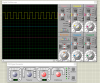
f. Sketch the observed waveform below. Label both axes and ground.


**broken link removed**


Output Waveform for Step #4


5. Generating and measuring triangle waveforms.

a. Set the frequency generator to output a triangle wave ( **broken link removed** ) with a frequency of 1.0 kHz.


b. Set the oscilloscope to 2.0V/div and 200 μsec/div and sketch the output below. Label the axes and ground.


**broken link removed**


Output Waveform for Step #5


c. Measure and record the values below, including units.


Vertical scale _____________ Horizontal scale______________


Period ________________ Frequency _________________


6. Generating and measuring sinusoidal waveforms.


a. Select a sine wave output with a frequency of 1 kHz.


d. Record measurements displayed on the oscilloscope display, including units.


Vertical scale _____________ Horizontal scale______________


Peak +V = _______ Frequency = ________________
 
This is a 5v 1Khz signal on a time base of 0.5 mS set to 2v/div
Is this what you see..
 

Attachments

  • Capture.png
    Capture.png
    97.7 KB · Views: 190
something like that but on my scope where do i set them setting at at the bottom of the screen or use the arrows
 
If you can see 10 pulses on the screen when 0.5 V/div is selected, then it represents 1khz..
Ian, I think you are mixing up the axes?
JimB
 
Status
Not open for further replies.

Latest threads

New Articles From Microcontroller Tips

Back
Top