Continue to Site

Welcome to our site!

Electro Tech is an online community (with over 170,000 members) who enjoy talking about and building electronic circuits, projects and gadgets. To participate you need to register. Registration is free. Click here to register now.

  • Welcome to our site! Electro Tech is an online community (with over 170,000 members) who enjoy talking about and building electronic circuits, projects and gadgets. To participate you need to register. Registration is free. Click here to register now.

Missing pulse detector

Status
Not open for further replies.

upand_at_them

Active Member
I'm looking to build a missing pulse detector to capture a fault with my microcontroller circuit. I currently have it flashing an LED, but I want to detect when it no longer flashes.

The 555 version of the following looks like a good means for that:

ETO Articles - Missing Pulse Detector (Watchdog Timer) Circuits Using LM339/393, CD4093, or 555 2017-04-15
1554833654045-png.117585


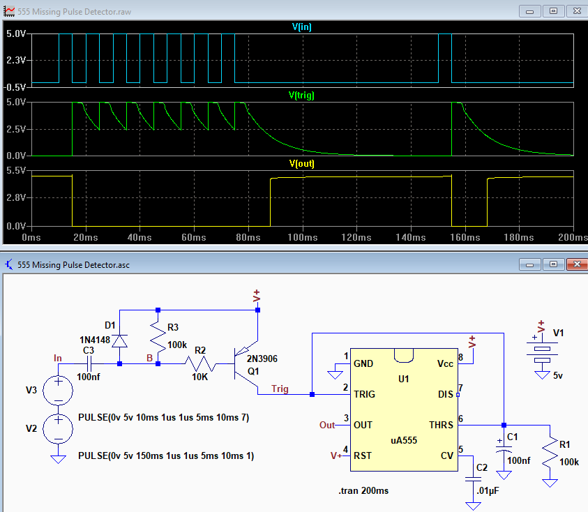
Is "uA555" a specfic part reference? I have a bunch of old Hitachi HA17555 timers. Will this work? I plan on using 10uF for C1 to get ~1.3 seconds trigger.
 
" Hitachi HA17555 "

The 7 in the part number might indicate that this is a CMOS version of the 555. If you do not need a 200 mA output stage, it should make no difference.

A long-time problem with the 555 is that it is not a true form of either type of monostable, retriggerable or not. In your circuit the 555 is nothing more than a comparator. As such, it could be replaced with any inverting logic gate or any single-supply opamp or comparator (if there is a spare one floating around in the design. An LM393 can replace both the 555 and the 3906, but it has an open-collector output stage.

ak
 
Why would you add a 555 to a microcontroller circuit? - if you want an external 'missing pulse detector' just use an 8 pin PIC to do it, making the 'circuit' consist of the PIC and pretty well nothing else, except a little simple software.
 
Why would you add a 555 to a microcontroller circuit? - if you want an external 'missing pulse detector' just use an 8 pin PIC to do it, making the 'circuit' consist of the PIC and pretty well nothing else, except a little simple software.

because he is a beginner and he would like to SEE his LED confirm the program is working as it should - or at least running through the loop and pulsing his detector.

don't criticize him, or make him explain himself, let him experiment.

also, why do you insist everyone use PICs? There are a dozen or more other microcontrollers in use. Or is PIC just easier for you to write and you really mean, any Microcontroller?
 
also, why do you insist everyone use PICs?
Oh .. Oh .. I know that one!

"I suppose it is tempting, if the only tool you have is a hammer, to treat everything as if it were a nail."

- Abraham Maslow, "The Psychology of Science: A Reconnaissance", 1966


ak - Maslow Antagonist
 
because he is a beginner and he would like to SEE his LED confirm the program is working as it should - or at least running through the loop and pulsing his detector.

He's wanting to use it to help debug an existing micro-controller project, so he's obviously got 'some' micro-controller experience, and by the look of things not much hardware experience?, so it's likely to much faster and easier to use a PIC and a few lines of simple code.

don't criticize him, or make him explain himself, let him experiment.

also, why do you insist everyone use PICs? There are a dozen or more other microcontrollers in use. Or is PIC just easier for you to write and you really mean, any Microcontroller?

PIC's are the most popular hobbyist controller, and what started it all, plus there are numerous small 8 pin ones (and even a fairly useless - in my opinion - 6 pin one :D )
 
PIC's are the most popular hobbyist controller,

wow, maybe 15-years ago.
Do a bit, just a tiny little bit, of research and you'll see how untrue that is in today's diy/hobby/maker world.
 
so it's likely to much faster and easier to use a PIC and a few lines of simple code.

if he has an IDE installed and owns a PIC programmer. Otherwise, it is about a half hour with a soldering iron and perf board. About the te it takes to download a pic ide.
 
There is a lot of "What you want to do is stupid. The way it has to be done is...."

Sometimes, some guidance (sans condescension) is needed (where the question just doesn't make sense, like switching a 220 volt 2kw load with a 2N2222 transistor), but many people are asking for help with a specific, realistic, way of doing things. In this case, it's a thought-out, valid approach. He shouldn't have to justify his reasons for wanting to do it that way, nor be ridiculed for his approach.

This may be why this forum is a collection of old farts and many posters never return after asking one question.

Suggesting alternatives is great. Saying that your approach is the absolute, must be done this way, only correct way to do it and any other approach is stupid is less than helpful.
 
Last edited:
I have extensive PIC experience. I was running into a problem with a PIC locking up and I wanted to catch it in the act. There was no definite time when it would happen, anywhere from a few seconds to a few minutes. Yes, I could have created a PIC circuit to do that, but that involves more than I thought necessary to accomplish the task. A 555 doesn't have to be debugged, firmware updated, or doubted that it will work. It just works. Caveman-simple things have their place. I don't have much "old school" electronics experience, I've only used a 555 a couple times. But I saw this as an opportunity. The "uA555" didn't come up in an internet search and I wondered if this was a specific requirement since the author could have written "555" instead.

I've since resolved the issue as a problem with the difference between I2C and SMbus levels. Sorry to waste everyone's time.
 
Status
Not open for further replies.

Latest threads

New Articles From Microcontroller Tips

Back
Top