Continue to Site

Welcome to our site!

Electro Tech is an online community (with over 170,000 members) who enjoy talking about and building electronic circuits, projects and gadgets. To participate you need to register. Registration is free. Click here to register now.

  • Welcome to our site! Electro Tech is an online community (with over 170,000 members) who enjoy talking about and building electronic circuits, projects and gadgets. To participate you need to register. Registration is free. Click here to register now.

minimum-parts decade counter circuit ideas ?

Status
Not open for further replies.

bob4bvm

Member
Can anyone suggest a minimum-parts decade counter circuit to drive 5 or 6 digit LED display ?
Needs to count up/down 5V pulses from a quad encoder. Pretty slow pulse rate, nothing over 10 kHz.
Typically i'd do this with TTL or CMOS decade counter chips using carry, but do not have room for all those stages. The old Intersil 6-digit LSI chips like 7226 do not seem to be available anymore.
Any other one-chip solutions out there ?
Thanks
Bob
 
  1. Get yourself an FPGA and learn either Verilog or VHDL to do the counter decoder in a single chip. The development tools will be a free download.
  2. Get yourself a microcontroller with an Arduino IDE and program the counter decoder in a C or Python like environment.
Pick your poison.
 
How much latency can you tolerate from one measurement to the next ?

One possibility (single chip) :

1659349994120.png


Basically use the quaddec component, 32 bits, (a component in PSOC land is an onchip resource)
and the led 7 display component. One possibility. Would take some code to periodically read
QUADDEC and write the RAM locations associated with each display digit. Design method is drag
and drop a component onto canvas, dbl click to config, and access datasheet for APIs description
used for that component. You then wire up part with a wizard (its routable internally and out to
pins).

Or use 7 LUTs (also onchip) and code them for BCD counting, 6 for count, 1 for binary to segment conversion. Or use basic logic onchip to create the equivalent of the 74HC90 BCD counter and
cascade those......Note you can create your own "component" by using schematic capture and/or
verilog. An example of community created components -


Here is whats on chip in standard chip library (multiples of many) -

1659349681492.png


IDE (PSOC Creator) and compiler free. Board to use possibly CY8CKIT-059 ($15) :

1659349813919.png


There are boards with a lot more I./O but seems you do not need that much.

I am not an experienced user of QUADDECs so here is the datasheet for the onboard component :


You could post at Infineon website for more complete help.


Regards, Dana.
 

Attachments

  • 1659349218716.png
    1659349218716.png
    222.7 KB · Views: 174
Last edited:
How much latency can you tolerate from one measurement to the next ?

One possibility (single chip) :

View attachment 138045

Basically use the quaddec component, 32 bits, (a component in PSOC land is an onchip resource)
and the led 7 display component. One possibility. Would take some code to periodically read
QUADDEC and write the RAM locations associated with each display digit. Design method is drag
and drop a component onto canvas, dbl click to config, and access datasheet for APIs description
used for that component. You then wire up part with a wizard (its routable internally and out to
pins).

Or use 7 LUTs (also onchip) and code them for BCD counting, 6 for count, 1 for binary to segment conversion. Or use basic logic onchip to create the equivalent of the 74HC90 BCD counter and
cascade those......Note you can create your own "component" by using schematic capture and/or
verilog. An example of community created components -


Here is whats on chip in standard chip library (multiples of many) -

View attachment 138043


IDE (PSOC Creator) and compiler free. Board to use possibly CY8CKIT-059 ($15) :

View attachment 138044

There are boards with a lot more I./O but seems you do not need that much.

I am not an experienced user of QUADDECs so here is the datasheet for the onboard component :


You could post at Infineon website for more complete help.


Regards, Dana.
Thank you Dana. This is fascinating, takes me into territory i have not been to yet !
About latency- do you think this would allow the readout to keep up with a pulse train of say 2 or 3 kHz ?
Also would need count to add/subtract based on up/dn counts (Ch.A/Ch.B) and also to reset to zero at the encoder Z pulse, .

This is for a telescope positioning readout, so nothing is happening all that fast, but would be nice if the display was near real-time.
Thanks,
Bob

Any microcontroller would do it, no problem, you're only looking for 'slow' responses to slow events - even very slow microcontrollers execute 1,000,000 instructions per second or (many) more.
 
Thank you Dana. This is fascinating, takes me into territory i have not been to yet !
About latency- do you think this would allow the readout to keep up with a pulse train of say 2 or 3 kHz ?
Also would need count to add/subtract based on up/dn counts (Ch.A/Ch.B) and also to reset to zero at the encoder Z pulse, .

This is for a telescope positioning readout, so nothing is happening all that fast, but would be nice if the display was near real-time.
Thanks,
Bob

The quaddec counts at 32 bit res to 28 Mhz, way overkill for what you are doing. More
than adequate to use.

The latency I was referring to is not the counting speed, rather the digit parsing and
write out to display, eg. updating the display. I think easily can do 10 Khz update rate.
Of course human eye cannot perceive this rate.

Yes on count up/dwn, and reset (thats a simple write).

Notice you could sub a more pleasing graphic display as there is onchip graphic controllers
to manage that. OLED that sort of thing. If you look at right hand column of IDE project I
showed only a small fraction of chip resources used. Lots left for other needs/wants in design.
Like battery monitoring, motor drive current monitoring (detect early lube failure), control and
monitor led pointer drive...........

By the way the PSOC 6 family would permit you to do all this in BLE if you so choose.


Regards, Dana.
 
Last edited:
Can anyone suggest a minimum-parts decade counter circuit to drive 5 or 6 digit LED display ?

For the speed you need, you don't need hardware quadrature counting, it's easily done in software.

Any even moderately fast PIC MCU would do it, though some in the motor control series do have hardware encoder interfaces.

The cheapest and with simplest construction would be something like a Seeed Xiao M0 MCU module - they are tiny, cheap and stupidly powerful (32 bit ARM CPU at 48MHz, with masses or RAM and flash).
eg.

Plus a serial/SPI interface display - there are many different types, with different numbers of digits or stackable modules to make any size display you need.


Or starburst rather than seven segment:
 
Thanks everyone ! You have given me so many good suggestions, i am having some fun just exploring them all. I am old enough that my electronics world included mostly the first generations of micro's (62xx, 65xx, ...) In my day most of this was still done with discreet chips logic TTL, CMOS, and LSI SP chips like Intersil and AMD used to make. I retired about the time the truly inexpensive uC's like PICs came on the scene. Most of my hobby stuff still relies heavily on non-programmable std logic chips, just because my bench is loaded with them and it was my world-view back when.

So it looks like you are dragging me kicking and screaming into the present day :) I appreciate your patience and assistance in bringing my designs up to date. No doubt i will have lots of questions from here on, but this particular phase of my telescope project is less critical to me than the build of the machine itself so can proceed at my own slow rate as i learn new things.
BR,
Bob
 
Learning barriers are actually getting easier.

Example kids in 6'th grade (and me) are using block programming languages
to do simple to, in some case, complex designs. Kids doing robot stuff. Here is
two examples of using block programming, a sophisticated timer and a talking
voltmeter. Look at the blocks and their flow, and you might be surprised you can
make some sense out of them. The blocks are then converted to code for you, and
the micro programmed.


Then there are devices like PSOC where you can do codeless logic designs. A chip
with various logic elements, that you drag and drop onto canvas, wire up, hit build
button, done. Like having your pile of chips and your breadboard, but inside a chip.
Note a small amount of code gets generated, but for codeless designs you do not
diddle with this.

Here is a simple example using mBlock to turn on something when a V is exceeded -

1659474438332.png


Read the blocks and the comments, its fairly obvious whats going on.

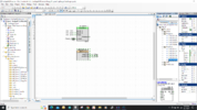
Now here is a codeless design using just logic elements inside PSOC tool -

1659473284260.png


This design has a 2 bit counter running at 1 Hz, and it cycles a 1 in 4 out mux, such that
each clock turns on one output to light one LED. No code written by user. Note dashed lines
indicate stuff/wiring is offchip. Note one R was used because only one led on at a time,
otherwise you would use an R for each led.

I could have added a push button, with a debounce block, that would cycle one led to the next
with each button push. Or used the button to start the counter, had it run once, and using a F-F
stopped it after it ran all 4 leds. No real limitation if you have been using discrete logic.

In the library of logic elements the community has added some 74HC components (you can easily
design your own component from scratch). In PSOC lingo a component is an onchip resource.
I recently did a component design, 64 bit Serial In Parallel out shift register to see if I could fit
it in the package (eg. # pins). That's a little more involved but you get the idea.

Notice resource window on right, hardly used any of the parts overall resources. A couple of %.

So in short you can do codeless designs and ease into programming as you go should you
choose to do so.

Board to use mBlock is Arduino Nano or Uno, former a $ 2 - $3 board, for mBlock. The PSOC is
board is a $ 15 kind of board. mBlock is free, tool for PSOC, PSOC Creator, also free.

Jump in with both feet, you will never regret it :)


Regards, Dana.
 
Last edited:
Status
Not open for further replies.

Latest threads

New Articles From Microcontroller Tips

Back
Top