Continue to Site

Welcome to our site!

Electro Tech is an online community (with over 170,000 members) who enjoy talking about and building electronic circuits, projects and gadgets. To participate you need to register. Registration is free. Click here to register now.

  • Welcome to our site! Electro Tech is an online community (with over 170,000 members) who enjoy talking about and building electronic circuits, projects and gadgets. To participate you need to register. Registration is free. Click here to register now.

Minimize Low Pass Filter Delay

Status
Not open for further replies.
I have a -10VDC to +10VDC signal coming into a PC. This signal is generated by a sensor that is measure very small movements. As the sensor is moved inward and outward the resistance changes causing a DC voltage anywhere inbetween -10V and +10V.

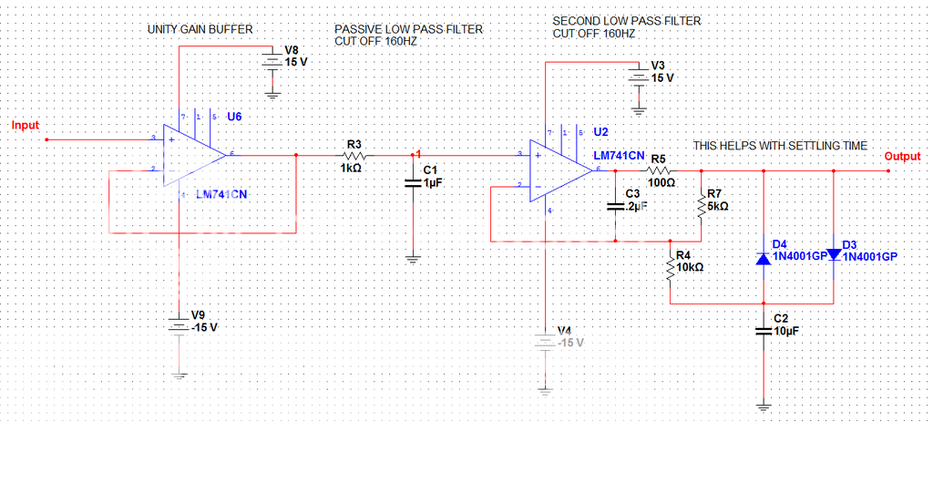
The excitation of the sensor is creating some high frequency noise. I am building a filter that contains an unity gain buffer opamp and a simple second order passive RC low pass filter.

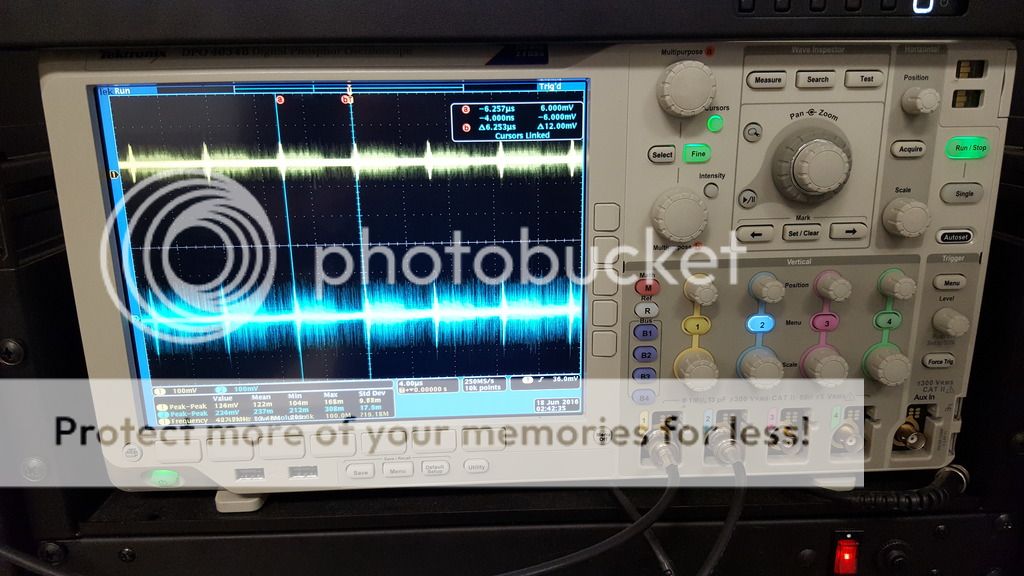
The filter is working well and I'm getting a clean DC voltage but there is a significant delay between the input and the output of the filter. It takes milliseconds for the output to reflect the input.

What ways can I minimize the delay?

Thank you!
 
What is the excitation frequency? Is it stable?
 
The excitation frequency is 3kHz and stable but there is all sorts of noise coming through too. I believe other noise is coming from some of the machinery in our test bench.

I built a low pass filter with a cut off frequency of 50Hz to try and just filter everything out. I know that maybe causing the slow response.
 
Last edited:
You could try analysing the noise to see if it's worth using one or two sharply-tuned notch filters to suppress dominant frequencies. Such filters might introduce less delay (though I'm no filter expert, so someone else could shoot that idea down :) ).
 
Fronm your description, and without seeing any waveforms..................It is not delay, it is called settling time.
The lower the cutoff frequency, the longer the settling time, all other conditions being equal.

You can play around with higher order filters and/or different filter responses (Butterworth, Bessel, Chebyshev and so on)
 
A passive second order filter is very slow. Use the buffer opamp to make a Sallen and Key second order Butterworth filter that is twice as fast and cuts noise better because it is sharper.
Noise into an audio amplifier is mains hum and it is prevented by using shielded audio cables. Maybe you need a shielded cable between the sensor and the pc.
 
You might be able to subdue the 3kHz (or other) fixed component of the noise by a cancellation method in which you compensate for the noise by subtracting a noise sample from the noisy signal, like this :-
NoiseCanceller.PNG
 
Ok so in simulation I was getting great results. Now in the lab I am getting 160kHz noise attached. The blue is the input and the yellow is the output. I also have attached the circuit I am using. The second low pass filter was taken from a TI paper which is here https://www.ti.com.cn/cn/lit/an/sboa011/sboa011.pdf

20160617_133456_zpswnrjvtmt.jpg

NOISE%20FILTER_zps4kebwpqp.png

TYPO IN CIRCUIT R4 = 1k as well^^^^^^^^
ALSO THE OUTPUT IS BELOW THE DIODES AND A OVE THE C2 CAP

So I attentuating some of the noise but it is still present. I have a few questions:
1. Why would the low pass filter allow 160kHz noise through when the cut off is at 160Hz?
2. Will the power supply noise powering the opamps effect the low pass filter?
3. The input has the 160kHz noise so I do not believe the power supply noise to the opamp is adding to it.
4. What should I look at next?

Thank you
 
Last edited:
How about getting some "real" opamps instead of a 40 year old pos.

Look up the PSRR of a 741 compared to something designed in the past few years.

If you want your active filter to attenuate 160kHz, then the opamp has to have some gain at 160kHz.

The 741 is about the absolute worst amplifier you could select for this job...
 
Last edited:
I don't like the filter.
U6 is a buffer.
R3, C1 is the only filter. What type of cap is C1? Why not 10k and 0.1uF?
U2 is not much of a filter. You can't get gain below 1 with a non inverting configuration. No help.
Are there any capacitors across the power supplies?
Why is 160khz passing through this "filter"?
----edited----
What input impedance is required? 10k? 100k?
Where is the signal coming from?
You want to remove 160khz.
Do you want to pass the 3khz? What is the highest frequency you want to pass with a gain of 1?
Do you have the grounds connected?
Is this on a bread board?
 
Last edited:
I agree that the lousy old 741 opamp should be buried. It was designed in 1968 (48 years ago!), is too noisy for audio and has trouble above only 9kHz. I think the LM324 and LM358 are worse.
The second opamp is not a filter, it is simply a noise generator and it passes any power supply high frequencies.
The very slow rectifiers are useless for audio, 1N4148 diodes should be used as level limiters.
 
I am wanting to pass a range of -10Vdc to 10Vdc no frequency basically, just straight Vdc value with a gain of 1.

The signal is coming from a sensor. We apply stress to a rock sample and measure radial expansion with a sensor that varies in resistance with movement causing a -10vdc to 10vdc value.

There is a lot of noise and i want to filter it out.

I want to filter the signal with out messing with the sensor circuit. Thats why i thought the buffer was necessary.

Ground are connected
Coming from a resistive sensor
Its on a breadboard
I need to still put caps on the power supply but the input also had the 160khz noise too even not connected to my breadboard filter
 
In my part of the world it is past bed time. So I can't do much now.
I think the first amp is passing the 160khz. But it is unhappy with a 1k load. It is working very hard to push 160khz into a 1k load. This power is coming from the supply with out capacitors. You need caps!. It might be that this noise got onto your power supply and runs to the second amp and out.

Add supply caps and try increasing the resistor to 10k and reducing the cap.

ALSO Add another RC to the input of the first amp. Get the 160khz off the first amp.
 
Here's your circuit revised to the correct values for two 160Hz corner filters and the output taken from the output filter capacitor per the TI design, not the op amp output as you incorrectly show.
Don't know where you got your values for the non-linear filter. :confused:
Note that the output is high impedance so you may need to add another buffer amp.
I show it with the 741's you have, which has adequate frequency response, but you should use a better op amp to minimize low frequency amplifier noise.

upload_2016-6-18_1-4-45.png
 

Attachments

  • Nonlinear Fast Rise Filter.asc
    2.2 KB · Views: 113
Good catch! I implemented the correct circuit but the drawing i attached is incorrect and has a typo.

Ill try the new circuit than you and ill let you know how it works!
 
Did you know that each wire and row of contacts on a breadboard is an antenna that picks up mains hum and all kinds of other interference? The parallel rows of contacts capacitive-couple signals that might cause oscillation. The contacts frequently are intermittent.
 
Should I also us the OPA627 for my filter? Whats a better opamp that you recommend?
The OPA627 is an excellent opamp but your filter is simply two RC filters with buffers instead of a sharp second order Butterworth active filter.
 
Status
Not open for further replies.

Latest threads

New Articles From Microcontroller Tips

Back
Top