Continue to Site

Welcome to our site!

Electro Tech is an online community (with over 170,000 members) who enjoy talking about and building electronic circuits, projects and gadgets. To participate you need to register. Registration is free. Click here to register now.

  • Welcome to our site! Electro Tech is an online community (with over 170,000 members) who enjoy talking about and building electronic circuits, projects and gadgets. To participate you need to register. Registration is free. Click here to register now.

Minimize Low Pass Filter Delay

Status
Not open for further replies.
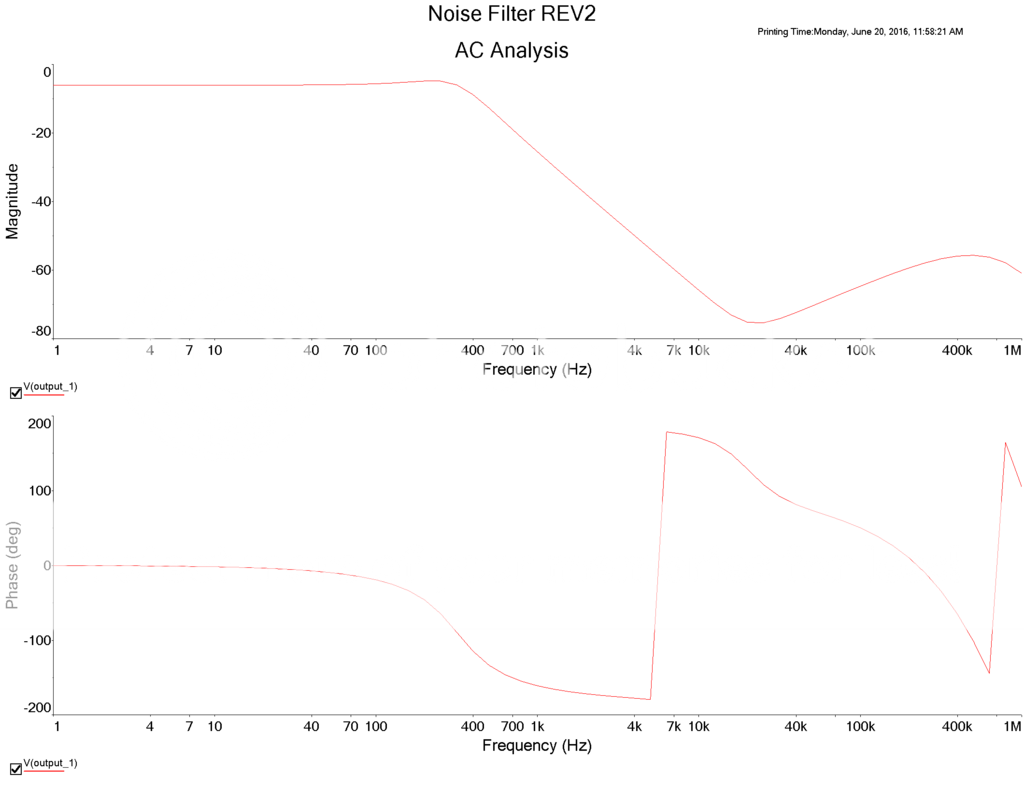
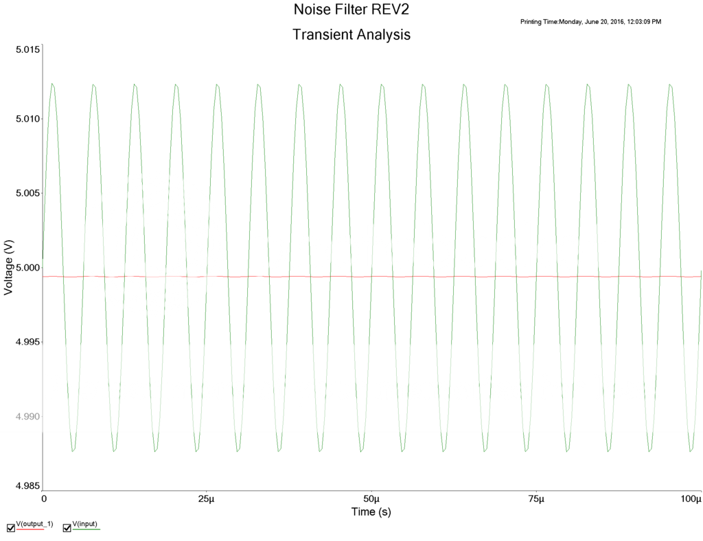
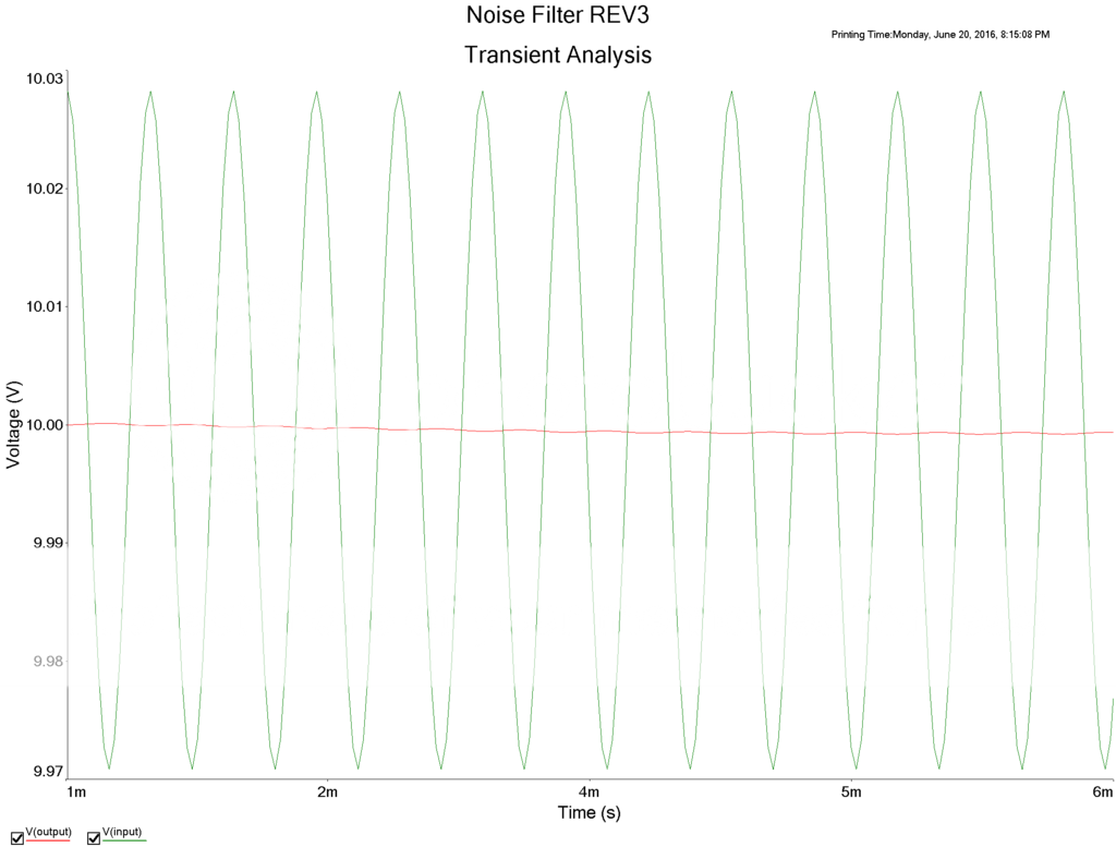
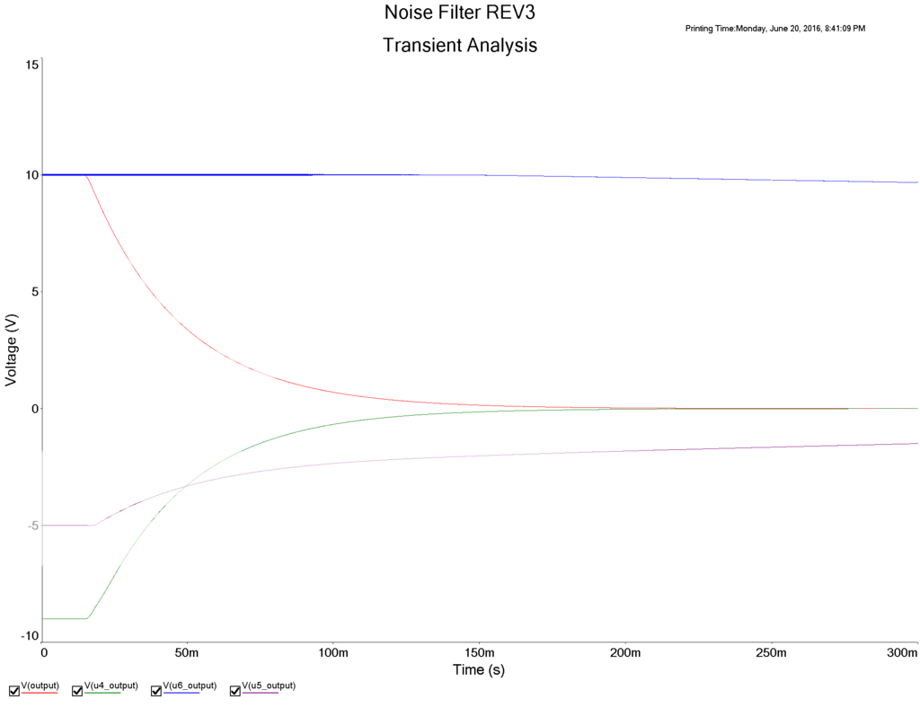
Should i not even us the TI portion? I need a settling time in the 50ms range or faster. I thought i might need it in order to help with settling time since my filter's cut off frequency is so low at 160Hz.

Should i do.
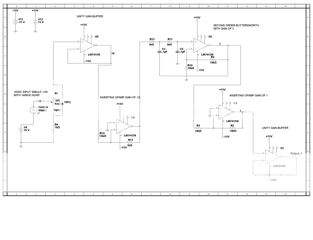
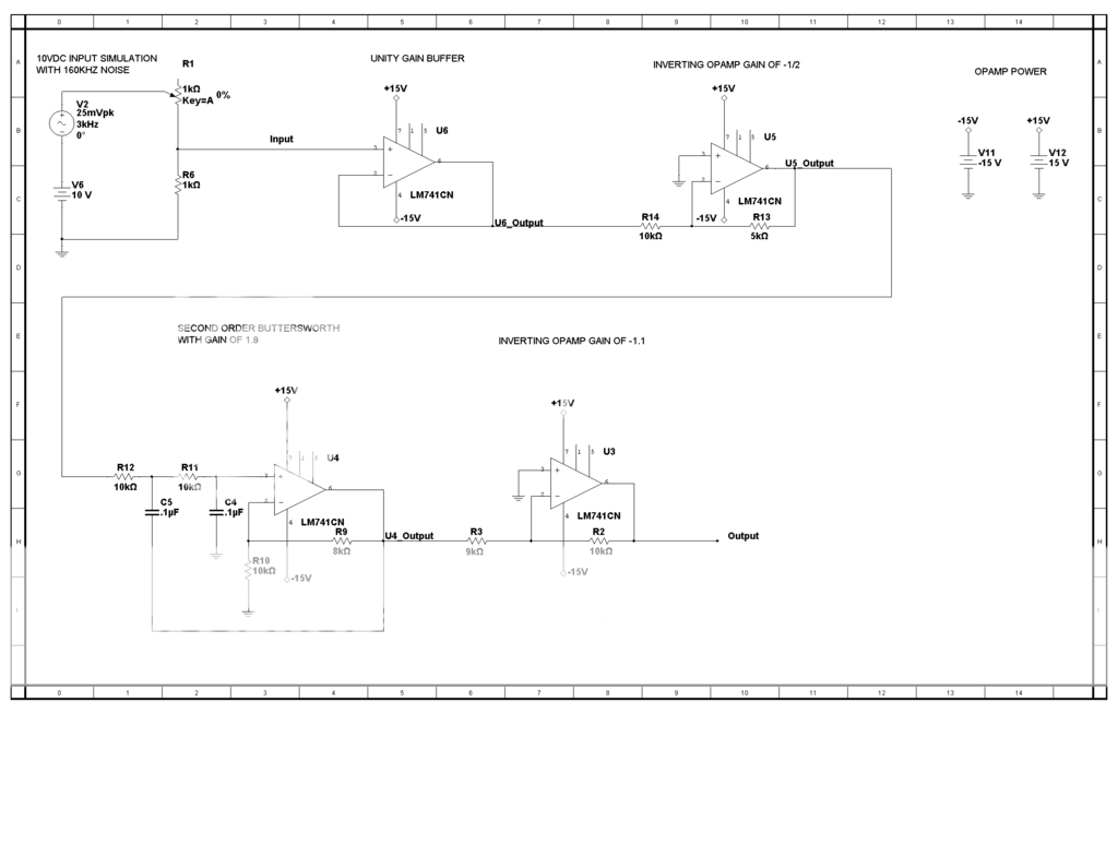
Buffer-->passive filter at 160Hz cut off-->active buttersworth at 160Hz cut off-->buffer again?

Or

Buffer-->passive filter at 160Hz cut off-->TI circuit im currently using at 160Hz cut off-->buffer again

Upgrade to the OPA opamp?
 
The OPA627 is an excellent opamp but your filter is simply two RC filters with buffers instead of a sharp second order Butterworth active filter.
Except that the second filter minimizes settling time for a step voltage input.

Edit: For fastest transient response, the first stage should be a duplicate of the second stage.
Of course it would still have the softer corner roll-off of two single-pole filters in series but the high frequency rolloff is the same as a Butterworth.
 
Last edited:
If you don't have a better op-amp, just fix the errors and see what happens. You can do that with out ordering parts. If that works then stop. If not then replace the amps.

There is a place called perfect, and another place called good enough. They are usually far apart.
 
Im using a RB-0515D to power the opamp, it has a +-5% accuracy on the output of +-15V. Should I be conditioning the output of this power supply?

I'm using just a 5Vdc source that also has a little ripple to feed the RB-0515D.

Would this have an impact on the filter?
 
Any half-decent opamp has excellent power supply hum and noise rejection so that voltage regulation is not needed when the input is biased at 0V. Also, accurate power supply voltages are not needed.
 
Ok so I re designed the circuit completely. See Below
Noise%20Filter%20REV2_zpsxzuj4tfv.png

Noise%20Filter%20REV2%20AC_zpslsfviymz.png

Noise%20Filter%20REV2%20Transient_zpso5jshkyw.png

So everything is looking good so far but then when I run a longer transient and look at the input and output. The output starts to just randomly decay????? Whats going on check it out below.
Noise%20FIlter%20REV2%20PROBLEM_zpscxvnbfa2.png

The above was a simulation at 1 volt but it does the same thing throughout the whole range of voltages -10VDC to 10VDC.
 
Your filter caps, C4/5, take time to charge initially.
 
I am using Multisim and my intial conditions are set to "Calculate DC Operating Point" and not "Set to Zero". So doesnt that mean the Caps are already charged?

Why would it run fine for 16ms and then start to decay?
 
Could you post the manufacturer and part number for the sensor you are using? Normally for sensors, an instrumentation amp is used as it has good common mode rejection (CMR), and has differential inputs which would most likely solve some of your interference problems.
 
I am using Multisim and my intial conditions are set to "Calculate DC Operating Point" and not "Set to Zero". So doesnt that mean the Caps are already charged?

Why would it run fine for 16ms and then start to decay?
Don't see any obvious reason for the decay.
Look at the source output and the output of each op amp to see where the decay is starting.

Op Amps U1, U3, and U5 serve no useful purpose. They are not needed and will just add noise to the signal.
 
Should I also us the OPA627 for my filter? Whats a better opamp that you recommend?
OPA192, OPA2192, OPA4192. (https://www.ti.com/lit/ds/symlink/opa192.pdf) would be more suitable and cheaper.
If you are going for wide-band opamps, especially the OPA627, you will need to be very careful about layout, decoupling, and isolation or you will get frequency instability.

Can you configure a balanced output from the transducer? If so you could have a balanced regime which will greatly reduce interference, both electro static and electro magnetic.

spec
 
Did you notice that your lowpass filter boosts frequencies near the crossover frequency a little? Do you like that error? Then it is not Butterworth.
The boost is caused because you have an equal values Sallen-Key filter with its gain higher than 1.6. If the gain approaches 3 then it oscillates. Instead make the filter opamp a follower with a gain of 1 and use two 0.1uF capacitors in parallel to make 0.2uF for C5 then it will be Butterworth.

Why do you have so many opamps? The first opamp U6 is needed as a buffer because the first resistor in the filter must be fed from a low impedance. But why two inverting opamps and why buffer the extremely low output impedance of the filter opamp?

So make the gain 1.5 or lower, R9 = 5k and get rid of the last buffer opamp circuit.

Well I did the inverting opamp amp because the filter had a gain of 2 and it was clipping since my max input voltage is 10V making 20V out the filter, so the filter was clipping at 15V since thats the power supply of the opamp. I did the inverting opamp in order to get a 1/2 gain before the filter doubles it, so it would not clip. Is this an inefficient thing to do?

I'm basically needing the filter to return the same value thats being inputted but with out noise, -10Vdc to +10Vdc.
 
Could you post the manufacturer and part number for the sensor you are using? Normally for sensors, an instrumentation amp is used as it has good common mode rejection (CMR), and has differential inputs which would most likely solve some of your interference problems.

The excitation device of the sensor is a Validyne (very old) and the sensor is a
sensor_zps2go9skjh.png

This is all the info I have, other than its -10VDC to 10VDC rang signal and that it has some noise they want to filter out before it gets to PLC.
 
OK new circuit REV3 with AC sweep and transient.
Noiser%20Filter%20REV3_zpsdepl5ml3.png

Noiser%20Filter%20AC%20REV3_zpslybfkmjs.png


Noise%20Filter%20REV3%20Transient_zpsdbuia2i6.png

Looking much better! This is simulating at 3kHZ but I did notice when I go up to 160kHz or higher thats when I start getting that weird decay on the output. It goes below the 10VDC that is also connect...Not sure if its a simulation error or whats going on. Ill run some more simulations watch each sections output to see whats happening.
 
m using a RB-0515D to power the opamp
What is the ripple on the power supply look like? The data said it could be 75mV. The power supply is probably switching at 160khz and is the noise source.

I could not find the "power supply rejection ratio at 160khz" but I think high frequency noise on the supply will pass to the output.

How long are the wires from sensor to op-amp?
 
Here is a transient when I set the simulated AC noise to 160kHz. I have each section of the circuit graphed.

WHATS GOING ON HERE? Even the U6 buffer output starts to get pulled down. I ran the transient for .3sec which took about 10mins in real time.
Noise%20Filter%20REV3%20160kHz%20Weird_zpsksjreirv.png
 
To test if the supplies noise is passing from Vcc to output; connect input to ground and look at the output.

There are many ways to pick up noise.

>Three foot wires might be part of it. I would use twisted wires.
>OR
>Use both outputs. Return 1, 2. They should have the opposite information. A input amp that has a function like this will help. (Return1 - Return2) If there is noise it should be subtracted out.
 
Status
Not open for further replies.

Latest threads

Back
Top