Continue to Site

Welcome to our site!

Electro Tech is an online community (with over 170,000 members) who enjoy talking about and building electronic circuits, projects and gadgets. To participate you need to register. Registration is free. Click here to register now.

  • Welcome to our site! Electro Tech is an online community (with over 170,000 members) who enjoy talking about and building electronic circuits, projects and gadgets. To participate you need to register. Registration is free. Click here to register now.

Minimal component TRIAC firing

Status
Not open for further replies.

xenomorph

New Member
Hello,
i am slowly charging a capacitor and when it reaches a voltage level of
18 Volts, i want to dump the capacitor charge into a battery with a TRIAC.

My approach is to use as minimal components as possible.
I know it could be easily done with a 555 timer etc. but the challenge is
to control the TRIAC firing with the voltage level on the capacitor.
I have not found a solution like that in the web.

So i am looking for brain-storm help to realize this.
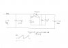
I was thinking to use a zener diode of 15 Volt rating sort of like a switch.
The problem that i am seeing is that once the zener conducts, the capacitor
will discharge itself through that path and drop in voltage and drive the zener
out of the conductive state BEFORE the current becomes high enough (30 mA) to create the gate impulse for the TRIAC.

A schematic to illustrate that:
**broken link removed**

I plan to use an optocoupler to trigger the TRIAC.
All i need is to get the TRIAC to fire somehow when the cap voltage is 18V. :confused:

Maybe there is a more elegant solution?
I would really appreciate some ideas on how to tackle this.
Thanks a lot
 
well while i suspect you are trying to charge from a solar panel and your approach is doomed the answer to your question is a 5V or so zener to the gate.
 
I think a simple comparator should do for driving your triac. There are some comparators that use only a few microamps so will not load your capacitor, requiring only picoamps for input current. When the capacitor reaches a threshold voltage, which you set with a pair of resistors (which can be a very high combined series resistance) acting as a voltage divider, the comparator output goes active, triggering the triac. A capacitor is placed between the output of the comparator and the gate of the triac so that the gate trigger current is only a short pulse for two reasons. One, so as not to waste charge from the main capacitor by continued gate current, and, two, so that as the voltage of the capacitor drops, it won't matter that the comparator output goes inactive when the threshold is no longer breached. The triac will remain in conduction until no more current flows from the capacitor to the battery, and the cycle is self-repeating.
 
Last edited:
Thanks Ubergeek63 and ccurtis!

I think the comparator idea sounds promising.
Never used one, so would the circuit be something like this ? :

**broken link removed**

To avoid too early current flow, maybe with a zener diode :

**broken link removed**

Or with the DIL-8 comparator pin assignment:

**broken link removed**

Is that what you have meant ccurtis?
 
Last edited:
I don't think that comparator circuit will work. The comparator +ve input is always held above its -ve input. Perhaps you meant to connect a reference voltage to the -ve input (such as the 12 battery), and the resistor divider to the +ve input?

You might have a problem with the triac latching and staying on forever; have you had a look at the holding current specification? It's 5mA, so if your charging current is > 5mA, then the triac will stay on. This may be overcome by putting a resistor from the gate to the most -ve leg (the one going to the battery).

Ubergeek gave you a very simple solution - just a single 5v zener from the 18v to the triac gate - sounds like that would fulfill your quest for "Minimal component TRIAC firing"
 
Very nice of you to provide schematics. You almost have it. You don't need the zeners at all (such as in your bottom circuit), because the comparator inputs draw so little current you can use very large resistors, drawing very little power. I failed to mention to use a comparator with a built in reference source for you to connect to the - input of the comparator. The resistor divider is set so that the voltage at the junction of the two resistors (connected to the + input) is equal to the reference voltage when the voltage on the capacitor is at a level you want the triac to turn on at. Maxim makes micropower comparators with built in references. Just make sure the comparator can work with a power supply voltage up to your +18V from the capacitor, otherwise, you will need a zener to limit the supply voltage for the comparator.

Edit #2: Opps, I'm sorry, you did use a comparator (MAX931) with a built in reference, and you did include a zener to limit the supply voltage to the comparator. That was not obvious to me, and I was presumptuous not to check before I opened my mouth. You still can dispense with the zener on the left. Two things left concern me. The zener for the MAX931 should be 7V or greater since 11V is max for the MAX931 and you have an +18V supply. I would prefer a comparator that can go to +18V if there is one. You may find that a bypass capacitor is needed accross the V+ and V- pins. Try without it first. And, I am not sure the triac will trigger the way it is placed in the circuit. The trigger voltage should be across the gate and one of the other triac terminals. It may still work the way you have it. I need to think on that. I don't like putting the triac between the battery negative and ground, either, because then you would lose your common ground.
 
Last edited:
You might have a problem with the triac latching and staying on forever; have you had a look at the holding current specification? It's 5mA, so if your charging current is > 5mA, then the triac will stay on. This may be overcome by putting a resistor from the gate to the most -ve leg (the one going to the battery).

This is a definite concern. With the comparator idea, the holding current must be selected so that the triac (or SCR) stays turned on for as long as required.

Ubergeek gave you a very simple solution - just a single 5v zener from the 18v to the triac gate - sounds like that would fulfill your quest for "Minimal component TRIAC firing"

As I understood the OP, the leakage current through the zener was enough to discharge the capacitor without ever providing enough gate current to turn the triac on.
 
@dougy83:
Thanks for your comment.

I don`t know if it could really be that simple:

**broken link removed**

I forgot to mention that the capacitor is being charged up very slowly
from 0V to 18V
and until it is fully charged the TRIAC should not fire.

The idea of the zener was to start current flow at a voltage higher than the battery voltage (18V) and to limit the TRIAC gate voltage.
Just using ONE 5V zener diode would fire the TRIAC already at a capacitor voltage of 5V and not 18V (Not sure if above circuit would even work, the zener path has no potential difference in it that i can see)

@ccurtis:

The schematic was probably wrong, i was just trying to integrate your suggestion quickly. With the zeners i tried to prevent a capacitor discharge (even if small) through the resistors until the TRIAC fires. It might take like 30 seconds for the cap to reach 18V. I can try it without the zeners and will see if it works well. I will try to find a Maxim IC with internal reference.

About the holding current, i assumed that when a 18V cap discharges to a 12 V battery the discharge current would be above 5 mA.
When the cap reaches 12V (i.e. the battery voltage) then the electric fields of the cap and battery are equal and the TRIAC can switch off so the cap voltage will rise again to 18V. It´s like a step charging process.
 
Just one little point, why are you using a TRIAC? - as it's DC a thyristor (SCR) is what's called for.

Does it really matter? A triac should work just the same as an SCR in that configuration.

Just using ONE 5V zener diode would fire the TRIAC already at a capacitor voltage of 5V and not 18V

Not quite, the triac will fire when >5mA flows through its gate to that other terminal. The voltage across the battery is 12V, the voltage at the triac gate will be about 1 volt above that (13V), and the voltage at the zener cathode is 5V above that (18V). But you're most likely right that the circuit is too simple to operate correctly. It should fire if the charging current is >5mA (but there's also the problem of the latching forever).

Is there any reason that you're not using a PNP or P-MOSFET as the pass element? That won't have any problems with latchup, and you can control it with a comparator (w/ hysteresis) very easily. It'll also dissipate less heat than the triac.
 
Last edited:
Is there any reason that you're not using a PNP or P-MOSFET as the pass element? That won't have any problems with latchup, and you can control it with a comparator (w/ hysteresis) very easily. It'll also dissipate less heat than the triac.
there actually is no problem with latch up as long as there is enough current to fire the SCR.

when the zener region is reached the SCR fires. when the cap is discharged the SCR is reverse biased and shuts off.

Dan
 
I have tried the variant to connect the zener diode directly to the TRIAC gate, but the voltage between anode and cathode of the zener is zero, because the gate is not connected to anything. So this method won`t work.
I have made a video of that minimal setup:

YouTube - Minimal component TRIAC triggering

I try to stay away from MOSFETs because i was not sure if the fact that no
pin of the MOSFET would really connect to a common ground would necessitate a complicated bootstrapping/MOSFET driver approach.

The TRIAC just needs a short gate impulse and keeps its connection open (as long as the holding current is sufficient) and with the initial zener approach it was to be expected that the gate impulse conditions will only
exist for a short time window, not long enough to keep a MOSFET open.

Looks like i have to test the comparator setup now.
 
@ccurtis: The schematic was probably wrong, i was just trying to integrate your suggestion quickly. With the zeners i tried to prevent a capacitor discharge (even if small) through the resistors until the TRIAC fires. It might take like 30 seconds for the cap to reach 18V. I can try it without the zeners and will see if it works well. I will try to find a Maxim IC with internal reference.

Look at my edit #2 above. I think your bottom schematic with the MAX931 is good to go actually, except use a 9 or 10 volt zener (instead of the 5V zener) so that your triac gate voltage will have a greater magnitude. I would get rid of that zener on the left, unnecessary part. The reason for a Triac instead of an SCR is that the Triac will fire with a negative gate voltage relative to MT1, which is what you have there. The circuit has other applications. Please let me know how it works in practice, should you build it.
 
Last edited:
i know this is ancient, but here is a design that i've been using for years
 

Attachments

  • scr switch001.jpg
    scr switch001.jpg
    386.7 KB · Views: 161
  • AC cap dump charger.JPG
    AC cap dump charger.JPG
    274.2 KB · Views: 155
One thing all of these circuits is missing is a resistor between the gate and MT1 (or cathode in the case of an SCR). The purpose of the resistor is to keep the device from turning on because of leakage current or fast voltage transients. Just thought this might be helpfu.
 
Status
Not open for further replies.

Latest threads

New Articles From Microcontroller Tips

Back
Top