eblc1388
Active Member
Edited later: The mouse modules now works in Windows.
Original post:
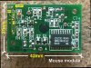
I have obtained an unknown mini (27mmx40mm) trackball module from a surplus store. It is similar to the one that is commonly found on laptops computers. The module has no push button fitted.
It has all the usual X and Y-axis opto-interruptors circuitry and a SMD Zilog microcontroller fitted with a 8MHz resonator.
On the module there is a 8-pin connector. I have identified that one pin is (+) & another two pin is (-). All remaining 5 pins connect to separate pin of the uC.
After powered up with 5V, the crystal clock is found to be oscillating by a logic probe so the uC is running. so far so good.
Of the 5 unknown pins on the connector they all show logic HIGH of some 4V. To identify if they are input or output, I parallelled a 12K resistor from the pin to 0V. Three of the pins' voltage dropped to 0.3V and the remaining two dropped to 3.7V. Therefore all these pins are input but with different values of pullup resistors. I also believed that the three pins that has its voltage dropped to 0.3V could be for the mouse push buttons connections.
When I move the trackball, four other pins of the uC show activities on a logic probe so these would be signals input pins for the X & Y axis movement sensors and the senors are working. However, there was no activity whatsoever on the two unknown pins on the connector which I believe is the DATA and CLOCK pin for the PS2 connection.
Questions: (edited: now with answer)
1. How to identify which pin is which as I don't want to just plug it into my PC and risk damaging my PS2 port?
Ans: No need to identify. Only two choices, pick one and check for correct mouse functioning in operating system with trial and error method.
2. Is the PS2 bus operates similar to I2C bus whereas connected devices can only pull the line level LOW instead of driving it HIGH?
Ans: The PS2 bus nature allows pulldown on Clock & Data line only. So a wrong connection is very unlikely to damage the bus. Nevertheless, I have inserted 220 Ohm resistor in series in both lines just in case something unexpected happened.
3. Does the uC waiting for some initiating codes be sent from host before outputting anything?
Ans: Yes, otherwise mouse would not report back movement data.
4. Any other suggestions?
I have attached an image of the module with pinout info in case someone might need it.
Added: I have located this webpage which gives me a lot of info to move on.
**broken link removed**
Original post:
I have obtained an unknown mini (27mmx40mm) trackball module from a surplus store. It is similar to the one that is commonly found on laptops computers. The module has no push button fitted.
It has all the usual X and Y-axis opto-interruptors circuitry and a SMD Zilog microcontroller fitted with a 8MHz resonator.
On the module there is a 8-pin connector. I have identified that one pin is (+) & another two pin is (-). All remaining 5 pins connect to separate pin of the uC.
After powered up with 5V, the crystal clock is found to be oscillating by a logic probe so the uC is running. so far so good.
Of the 5 unknown pins on the connector they all show logic HIGH of some 4V. To identify if they are input or output, I parallelled a 12K resistor from the pin to 0V. Three of the pins' voltage dropped to 0.3V and the remaining two dropped to 3.7V. Therefore all these pins are input but with different values of pullup resistors. I also believed that the three pins that has its voltage dropped to 0.3V could be for the mouse push buttons connections.
When I move the trackball, four other pins of the uC show activities on a logic probe so these would be signals input pins for the X & Y axis movement sensors and the senors are working. However, there was no activity whatsoever on the two unknown pins on the connector which I believe is the DATA and CLOCK pin for the PS2 connection.
Questions: (edited: now with answer)
1. How to identify which pin is which as I don't want to just plug it into my PC and risk damaging my PS2 port?
Ans: No need to identify. Only two choices, pick one and check for correct mouse functioning in operating system with trial and error method.
2. Is the PS2 bus operates similar to I2C bus whereas connected devices can only pull the line level LOW instead of driving it HIGH?
Ans: The PS2 bus nature allows pulldown on Clock & Data line only. So a wrong connection is very unlikely to damage the bus. Nevertheless, I have inserted 220 Ohm resistor in series in both lines just in case something unexpected happened.
3. Does the uC waiting for some initiating codes be sent from host before outputting anything?
Ans: Yes, otherwise mouse would not report back movement data.
4. Any other suggestions?
I have attached an image of the module with pinout info in case someone might need it.
Added: I have located this webpage which gives me a lot of info to move on.
**broken link removed**
Attachments
Last edited:
