Hi guys,
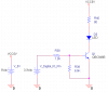
I have a TL072CN OP-Amp chip, As you know most of datsheets indicate 2 values (Min & Typ). the gain of the siad op-amp with the configuration I have used is 101 (1+1M/10k).
Now I am not sure which parameters should be used (Min or Typ) to calculate the GBP?
Thanks for any help
I have a TL072CN OP-Amp chip, As you know most of datsheets indicate 2 values (Min & Typ). the gain of the siad op-amp with the configuration I have used is 101 (1+1M/10k).
Now I am not sure which parameters should be used (Min or Typ) to calculate the GBP?
Thanks for any help
")
")