Continue to Site

Welcome to our site!

Electro Tech is an online community (with over 170,000 members) who enjoy talking about and building electronic circuits, projects and gadgets. To participate you need to register. Registration is free. Click here to register now.

  • Welcome to our site! Electro Tech is an online community (with over 170,000 members) who enjoy talking about and building electronic circuits, projects and gadgets. To participate you need to register. Registration is free. Click here to register now.

Micro welder

Status
Not open for further replies.
The timing circuit I used for my MOT welder was based on a circuit from MIT. As I mentioned above, the datasheet for a 555 will show how to wire it as a monostable to give a single pulse that will activate your relay for the desired time. The trigger (TR, pin#2) for the 555 must be brought low (i.e., grounded) to initiate the timing. If the trigger is held low, the 555 can continually reset. The **broken link removed** solves that problem and adds debouncing. (Edit: That link to the MIT site appears to be broken, or my ISP is not working right. Sorry about that.) The latter prevents multiple pulses (or an uncertain pulse duration), which can be caused by bouncing of the switch contacts as they close.

mot-switch-timer-png.36257


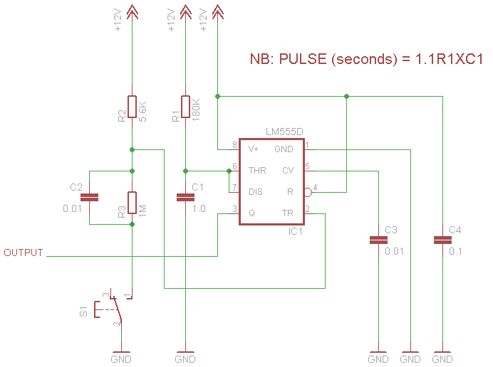
How it works is explained fully on the MIT link. In brief, when S1 is closed, the circuit from your positive supply is completed across C2, which acts briefly as a short to ground and initiates the trigger. As C2 charges, the voltage at the TR pin increases because of the voltage divider formed by R2 and R3. Thus, re-triggering is prevented if you leave the switch closed. Since we anticipate that the welding time (i.e., the pulse width) will be quite short, I believe that including that aspect in the circuit is important.

The attached schematic has values calculated to give about a 200 mS pulse (i.e., 10 cycles at 50 Hz). You can change the values of R1 and C1 as needed to get any pulse duration you want. I show a 12V power supply. A typical 555 (i.e., LM555C) can operate from 4.5 to 16V. For testing, I would suggest that you simply use a 9V battery. If that works, then you may want a longer lasting supply for routine use.

As for how to connect it, see the 5 Bears reference I gave above. It is really simple. The trigger circuit controls the relay, and the relay controls the input supply to your transformer.

John
 

Attachments

  • MOT switch timer.png
    MOT switch timer.png
    6.8 KB · Views: 2,281
Last edited:
jpan, I followed a link to that site, it's not a welder it's just a soldering iron. Might work well though as you can get silver solder.
 
I had a look at the puke2 operating instructions, looks like the voltage to go for is 20-38VDC; it also provides current up to 25A for up to 1.7 seconds. Sounds like overkill for tack welding.

You could also use a few 12V lead acid batteries connected in series, with an appropriate control (current + timing) circuit. Even SLA can provide up to 60A for short bursts.

Is it possible that the reason the voltage, current, and time are so high compared to welders meant for other metals is because the resistance of silver is so low compared to those other metals? I'm not sure, I just thought it made sense that it would take much more to heat it to the point of welding. Then again, these are some pretty small parts soooo......
 
Sorry, I meant the link to illustrate the sort of pincer device being discussed. You are correct, that device is for soldering. I suspect similar devices, particularly ones with tungsten electrodes, could reach temperatures necessary for hard soldering, brazing, and even tack/spot welding.

John
 
Since I had never welded silver, I searched on that question. In theory and by analogy to steel, welding silver should be quite easy, because its oxide (like that of iron) melts at a lower temperature than the base metal.

However, according to a research paper I found, it appears that oxygen is very soluble in molten silver. As the silver cools, the dissolved gas comes out of solution and can create a weak weld. One solution to that problem is to use a wet paste (like one may use in steel to limit heat distortion) next to the weld. The water vapor produced is sufficient to prevent porosity from oxygen. That is effectively a shielding gas, but its mechanism of action is quite different from the shielding gas used for aluminum, MIG, or TIG welding. A jeweler might routinely use such paste to protect other parts of the ring (etc.) from heat without realizing another purpose was also being served.

Anyway, I found that tidbit interesting.

John
 
While the O/P and the web site heading; **broken link removed** calls this a "spot welder" If you read the information given on the site you will see that in the text it is really a TIG welder. And that is what they call it in the description.

It uses a tungsten(wolfram in the text) electrode and Argon gas as a shield. Thats TIG welding!

If I was to do this project I would start with Gary Chemlec's "mark-space" generator; **broken link removed** driving a couple of Mosfets, switching the voltage from the transformer. That would give you a frequency and duty cycle (weld time) control real easy.

From there it would be pretty simple to add a flow timer and valve to control the Argon.

Just my dumb ideas on this. Cary
 
  • Like
Reactions: Pip
micro-tac-tig-fusion welder

Hi folks,I thought that with my first post someone could give me the info I needed to build jewellery tacker,they did ,special thanks to Jpan.However it seems to evolve somewhat,getting hooked.Just to put my Ha'peth in.Got into silver & gem cutting etc.5 years ago,built and experimented with home made equiptment.I did make a hydrogen/oxyen generator for micro torch,Which produces an incredibly hot flame of minute sizeThe flame from hho generator has very interesting properties but oxidisation is a problem.With all 925 silver a flux is needed to help the solder applied to flow and combine with parts to be joined.It also inhibits fire stain which is caused I believe by oxidisation of impurities in the alloy.999 purity silver does not have this problem.At this time I hope to go with 555 timer & solid state relay to produce ajustably timed pulse
of 3.2v approx 30A.After reading posts I think I may have more success going down the fusion road,using same basic unit to fusion tack as opposed to attempting a full weld.Thanks all for stimulation.
Kind regards ,Pip
 
To help reduce the appearance of the staining of the silver you could always have it silver plated afterwards, that would be relativly expensive though and if the silver plate wears down to the weld joint the staining will reappear, that's if it's actually in the metal. You could try a shielding gas but I don't know how you would rig such a device up. Shielding gasses wouldn't work with an oxygen based heat source though, you'd have to use an electrical arc or spot welder to get those kinds of results.
 
  • Like
Reactions: Pip
micro weld

Hi Sceadwain,Yes plating is an option although not usually nescesary, a dip in
diluted sulphuric acid clears most firestain,really stubborn stain is removed by abrasion and then polish.Plating does have its place on silver but rhodium plating for brilliance and durability (Expensive).Plating always does in my opinion detract from the original detail.Unless it is to be part of overall design appearance. Kind Regards, Pip
 
You'd have to put some seriously fine detail on a piece to cause plating to bleed out the detail, the thickness of typical flash coatings for appearance is only a few microns thick.
 
One neat micro welder I used to work on at an aerospace manufacturer used a stack of ni-cads in parallel and recharged between welds. If you short a ni-cad, it has a very high current. 10 in parallel would have extremely high current. Charge at 1 amp for 20 seconds would give 200 amps for .1 seconds. Fairly small, very powerful.
This was used to bond gold wire from chip to substrate.
kinarfi
 
Last edited:
  • Like
Reactions: Pip
Micro-weld

Hi Kinarfi, thanks for your input ,the unit you described sounds ideal for my purposes.Definately something I 'de like to try.
 
Use super caps instead. They have some low ESR models that have substantial capacitance. The only real hard part is to actually determine your needs, you need to know the voltage you need and the capacitance to get the desired energy, so it requires a bit of experimentation.
 
Well, there are people who make their own nickel-strip battery tab welders. They use several Farads at 12v-20v (high quality stereo "boost" capacitors, maybe several in parallel). They need VERY VERY low ESR because this process requires a surge of probably hundreds of amps. In fact a common transistor cannot really do this, instead they use a high current SCR which will latch closed and drain the capacitor to nearly 0v.

Silver- astronomically harder! Why? Well, for one, silver has a very low resistance- lower than copper- thus hundreds of amps will heat your copper electrode and wire more than it heats the silver joint. Second, silver has a very high thermal conductivity- higher than copper- any heat generated is whisked away from the fusion zone almost instantly.
 
Status
Not open for further replies.

Latest threads

New Articles From Microcontroller Tips

Back
Top