Continue to Site

Welcome to our site!

Electro Tech is an online community (with over 170,000 members) who enjoy talking about and building electronic circuits, projects and gadgets. To participate you need to register. Registration is free. Click here to register now.

  • Welcome to our site! Electro Tech is an online community (with over 170,000 members) who enjoy talking about and building electronic circuits, projects and gadgets. To participate you need to register. Registration is free. Click here to register now.

Micro tube amp (need help)

Status
Not open for further replies.

Zachary Phillips

New Member
  1. I'm trying to design a micro sized tube amp that would use two CK534AX vacuum tubes powered by a 9v battery.
  2. I understand that this is probably a silly thing to try and make the output will not be that much of an increase if any, but I want to make it anyways seeing as how I have a whole bag of these tubes.
  3. I also have the data sheet for this particular tube with all the values need for operation, but since in a novice in this trade i'm finding it difficult to figure out a circuit.
 

Attachments

  • CK534AX.pdf
    96.2 KB · Views: 182
It sounds a pretty silly idea to me, what sort of specification are you hoping to achieve?.

Presumably you've read the spec sheet?, and have noticed that maximum current is only 0.1mA at 9V that's only 900uW.
 
honestly if I can just get a 1 to 1 input to output that fine with me.

basically I just want to send the signal through the the tubes, the tubes are more just for looks but I would like to be able to say that they are actually being used.

also I somehow forgot to mention that I would have two 9v batteries for the
plate and screen grid

also here's the pinout for the tube.
 

Attachments

  • ck512ax_sock.png
    ck512ax_sock.png
    2.4 KB · Views: 166
Last edited:
So you're only talking about a preamp?, not an 'amp' as you initially said.

I think it's rather a crazy idea, adding extra parts just to lower the quality, but there's no reason you can't use those as preamps.
 
You might be able to use the tube as a preamp, maybe even tube distortion, however anything other than an earpiece you wouldnt hear much.
At least if you made a tube preamp you wouldnt necessarily need an output transformer, you'd need a high impedance op amp follower circuit on the op/p to buffer that to the amp or following audio device.
 
So what if i use a set of high impedance headphones would that work?

Honestly I'm more invested in just trying to figure out how to power the filament at this point more than the thing as a whole working, I've been messing with it for a few weeks now and I just want to know the best way to power it.
 
Are headphones made with an impedance of 5 Megohms?? Most headphones are 32 ohms but a few are 600 ohms.
63 years ago all audio products produced distortion so the datasheet for this little old tube does not even mention it.

Where will you get the 0.625V at 15mA required by the filament? One AA alkaline cell in series with a transistor can do it for a few days but the voltage will be dropping the entire time, unless you make a voltage regulator.
 
That's why i started this thread to see if someone could help me figure out a way to regulate the voltage to .625v / 15ma from a 9v battery and in general just to learn how to set up a tube amp / preamp, whatever.

If you can help me set up a circuit great, fantastic, thats literally all I want.
 
Sorry, I do not use or design antique parts and circuits.
Solid state amplifiers with vacuum tubes glowing on top (not part of the audio circuit) are sold to audiophools.
 
Unlike some others here on ETO I do have a penchant for industrial archaeology.

Here is my attempt at a schematic for a two stage amplifier:
CK534AX Amplifier.jpg

One of the original specifications was that it should use a 9v battery.
While drawing the schematic, I used an 18v supply which would probably be better, but 9v may be OK.

There is a need for a separate 1.5v supply for the valve heaters.
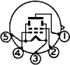
The heaters are rated at 0.625v which is why the 43 Ohm resistors are included in the connection to pin 3 of each valve to allow connection to a simple 1.5v cell.
I did initially consider connecting the two heaters in series, so making a 1.25v heater chain.
But small battery valves like these rely on the heater supply to provide the grid bias, which is why the filament connections are specified as positive and negative in the datasheet.
It may be possible to modify the circuit to a series heater arrangement, but I think that this would involve changes to the rest of the circuit, so lets just "Keep It Simple".

Be aware that this is what is known as a "voltage amplifier", it will not provide much output power.
The output impedance is high and will be loaded quite heavily when connected to an external low impedance load.

JimB
 
You are welcome.
In the unlikely event that you are passing near Peterhead, you owe me a bacon sandwich. :)

JimB
 
i've built an effects box that uses subminiature tubes. i have a bunch of 6BF7 dual triodes, and the stomp box uses two cascaded SRPP stages. an SRPP is a common cathode stage with the second triode in the tube used as a very loose current source plate load. i'll try to remember to upload a schematic for it later. it's powered by a 24V printer wall wart. with an SRPP stage, the triode that is the plate load acts as a current source. when you are operating a tube at less than 1/2 of it's normal plate voltage, you don't have a lot of gain. with the pentode you have, the max plate voltage is 30V, so a 24V supply or even an 18V supply would work well.
 
if you still want to try using a 9V power supply, you might find [this article] useful.
 
EEK! The article about using vacuum tubes at low voltages says that by adding 2nd-harmonic distortions out-of-phase with the existing pretty high 2nd-harmonic distortions (by using a "grid-stopper" resistor) actually reduces the total distortion. The article talks abut the "musical effect" of adding even harmonics distortion with the vacuum tube. They even show a very low distortion audio opamp driving the tube and another opamp at the tube's output so that there is plenty of even harmonics distortion.
 
Never mind AG, it could be worse...
He could feed it through a balanced modulator and a 300 to 3kHz filter to make it into SSB. :eek:
I can here those ducks quacking from here.

JimB
 
Status
Not open for further replies.

Latest threads

New Articles From Microcontroller Tips

Back
Top