Continue to Site

Welcome to our site!

Electro Tech is an online community (with over 170,000 members) who enjoy talking about and building electronic circuits, projects and gadgets. To participate you need to register. Registration is free. Click here to register now.

  • Welcome to our site! Electro Tech is an online community (with over 170,000 members) who enjoy talking about and building electronic circuits, projects and gadgets. To participate you need to register. Registration is free. Click here to register now.

Micro-controller controlled Spark plug

Status
Not open for further replies.

rabhishek91

New Member
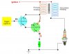
Hi. I am doing a project where i need to control the spark plug based on a condition. If a pin goes high, then the spark plug should function else it should be disable. I have attached the possible circuits which can be used to interface the spark plug with the Micro-controller.

In circuit 1 , they have configured the transistors as Darlington pair. Is it used to get high current gain?

In circuit 2, only one transistor is used for switching action. Can that transistor alone drive the circuit ? :confused:

Also in the programming part. Is enough if i just turn on and off the pin (as shown below) or should i use PWM ?

if(bit_is_set(PINA,0)) //Check high on pin0 of portA
{
PORTC|=(1<<PINC0); //Turn on the pin
delay_ms_(50);
PORTC|=(1<<PINC0); //Turn off the pin
delay_ms_(50);
}


Please help.
Thanks in advance :)
 

Attachments

  • Fuction generator and spark plug (1).jpg
    Fuction generator and spark plug (1).jpg
    45 KB · Views: 2,147
  • Sparkplug_circuit.png
    Sparkplug_circuit.png
    37.7 KB · Views: 1,129
hi
A vehicle Ignition coil draws approx 3 to 4 amps from a 12V battery supply.

In circuit #1, depending upon the value of R3, a 5V MCU output pin may not be able to drive the Darlington pair into saturation.

You also MUST consider some form of back emf snubber for the transistors,

On circuit 2, the 5V from the MCU must drive the MOSFET into saturation, also back emf protection is required,

Regarding just switching the driver ON/OFF, remember that the EHT spark is produced when the driver is turned OFF,

You must also allow sufficient ON time for the driver [dwell time[ to ensure the coil current has reached its maximum value.

E

Thanks for your reply sir.:)
"You must also allow sufficient ON time for the driver to ensure the coil current has reached its maximum value"- How to determine this time sir.

Also can i use a signal generator with square pulses instead of all these circuits and control the spark plug by controlling the voltage from battery using relay?
 
hi,
You could use a SigGen to drive a relay, but add a back emf protection diode across the relay coil to protect the SG

Also add a suppressor across the relay contacts.

The minimum dwell time could be determined using an oscilloscope measuring the coil current.
 
hi,
You could use a SigGen to drive a relay, but add a back emf protection diode across the relay coil to protect the SG

Also add a suppressor across the relay contacts.

The minimum dwell time could be determined using an oscilloscope measuring the coil current.

"The minimum dwell time could be determined using an oscilloscope measuring the coil current." - I think i have to start understanding from the scratch. Ok sir. I'll work on it.

Sir what is the function of suppressor ?
 
"The minimum dwell time could be determined using an oscilloscope measuring the coil current." - I think i have to start understanding from the scratch. Ok sir. I'll work on it.

Sir what is the function of suppressor ?

hi,
In cars that use contact breaker ignition coil drivers, a 2uF capacitor is fitted across the circuit breaker contacts, it helps prevent arcing across the contacts, which would shorten their life, also it helps 'tune' the coil inductance in order to enhance the EHT generation,.

EDIT:
A point to consider when using a relay is the operating and release times of the relay, which could be in the order of 10's millisec

Thanks for your time sir . It helped me a lot:) I'll work on it.
 
Code:
PORTC|=(1<<PINC0); //Turn on the pin
delay_ms_(50);
PORTC|=(1<<PINC0); //Turn off the pin
delay_ms_(50);
That Code wouldn't work. You turn on PORTC.0 2 times, so it is always switched ON.
 
Be careful in your choice of protection of the driver circuit. A relay as said would be the simplest way to switch the primary with an anti arcing cap across the contacts. It's the huge back EMF on the primary when the circuit is opened that induces the even bigger spark voltage in the secondary as the magnetic field collapses.

As for working out how the current maximises timewise in the primary, I wouldn't worry too much as ignition coils can run over a fair range due to engine speed using simple points as switches in older cars.
 
Status
Not open for further replies.

New Articles From Microcontroller Tips

Back
Top