Continue to Site

Welcome to our site!

Electro Tech is an online community (with over 170,000 members) who enjoy talking about and building electronic circuits, projects and gadgets. To participate you need to register. Registration is free. Click here to register now.

  • Welcome to our site! Electro Tech is an online community (with over 170,000 members) who enjoy talking about and building electronic circuits, projects and gadgets. To participate you need to register. Registration is free. Click here to register now.

Metronome

Status
Not open for further replies.

Powzoom

New Member
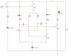
Hey, this one is really confusing me. I have an astable multivibrator using Q1 and Q2. Q3 controls the voltage to the capacitors so they charge equal and maintain the leds flashing at 50% Duty Cycle. This is for a metronome which flashes a red LED to indicate the 1/4 note beat (LED 1) and the a green LED to indicate the "and" beat (LED 2). Up to here it works fine, adjustable freq. with 50% D.C. but when I attach the speaker, it changes the Duty cycle or makes 1 LED flash and the other stay on contently. How can I connect my speaker to maintain a 50% cycle and hear a "CLICK" sound on every quarter note beat?

Any help would be awesome.

The resistor and cap values are slightly different then in the pic.
 

Attachments

  • LED.jpg
    LED.jpg
    48.4 KB · Views: 112
The speaker is driven by Q4. Q4 doesn't have a series base resistor so its base-emitter diode is shorting the collector of Q2 almost to ground.

Isn't LED1 lighting all the time and isn't the oscillator not working?
Add a 22k resistor in series with the base of Q4.
 
I figured it out. Q4 was drawing current from capacitor on one side. In order to trigger Q4 to saturate, I needed a significant amount of current. So, I used a darlington which requires much less current to switch and a couple of uA isn't even noticeable.
 
Go back to the thread where you got that circuit (I posted it). You need a diode in series with each emitter.
 
I figured it out. Q4 was drawing current from capacitor on one side. In order to trigger Q4 to saturate, I needed a significant amount of current. So, I used a darlington which requires much less current to switch and a couple of uA isn't even noticeable.
No.
The base-emitter diode of Q4 is shorting the collector of Q2 almost to ground which will turn on LED1 all the time.
Add a 22k resistor in series with the base of Q4.

Q4 still won't turn off so add a 10k resistor from the base of Q4 to ground.
the circuit should work with these two resistors added.
 
I forgot to mention that I had added the diode and resistor. Your right that it was shorting to ground. The circuit "works" with a 22k resistor and a normal bjt but it alters the charging time too much on the capacitor which throws off the duty cycle. I built it and saw it happen.

I measured 5v at the collector of Q2 when it switches on. My regular bjt had hfe(min) = 100. The transistor was rated for 0.8A, so Rc=Vcc/Ic which comes to Rc=9/0.8=11.25ohm. And Ib=Ic/hfe(min) according to a textbook I have, so Ib(min) to saturate transistor is 0.8/100= 8mA. 8mA is small but it still throws off the cycle.

When I use a darlington with hfe(min)=30k, rated at 0.4A Ic, I get Rc=9v/0.4A= 225ohm. Ib comes to 0.4/30k=13uA. 13uA is way less than 8mA. So I used a base resistor of Rb=Vc(from Q2)/Ib = 5/13uA = 384kohm. I use a value less than that because as the battery drains it won't be 5v at the Q2 collector anymore.

I've built this and it seems to work. Thanks for the help guys.
 
Status
Not open for further replies.

Latest threads

New Articles From Microcontroller Tips

Back
Top