Continue to Site

Welcome to our site!

Electro Tech is an online community (with over 170,000 members) who enjoy talking about and building electronic circuits, projects and gadgets. To participate you need to register. Registration is free. Click here to register now.

  • Welcome to our site! Electro Tech is an online community (with over 170,000 members) who enjoy talking about and building electronic circuits, projects and gadgets. To participate you need to register. Registration is free. Click here to register now.

measuring power of solar panels

Status
Not open for further replies.
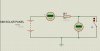
A recent issue of Circuit Cellar had an article modelling solar cells. They used a light dependent current source shunted by a diode whose forward voltage was relatively insensitive to the incident light.

Same here.
Solar cell - Wikipedia, the free encyclopedia

So, it seems current delivered (to a varying load resistor, with varying illumination) is a better indicator of output power than output voltage. Since things with coils are current controlled, I 'spose solar cells should be connected to motors, or loads that act like motors.

And a motor spinning an optical disk is a current to freq. convertor, so a counter keeping track of the pulse count is an amp-hour meter. With constant cell voltage it becomes a watthour meter.
 
Last edited:
why not just have 2 light sensitive resistors pointing away from each other (not sure of angle but guess 90+ deg) that way the circuit knows which way the sun is so can return to start at sunrise and when the difference between the two falls below a certain amount it knows that its now night.
 
Why not simply have the solar panel divide in two, with a vane standing between the halves. When the panel outputs are unequal, one is presumably being shaded by the vane and should be moved. Allowances should be made for the hopefully brief presence of clouds and birds.
 
why not just use solar panels for what they are meant and let sensors do their job ?

to do as you sa you will need to point the two panels in slightly different directions which will cause a powrr loss
 
Hi Friends,
There have a simple way to measuring the output power of solar panels.
You first measure an open circuit voltage of the solar panel (Voc), then you can calculate the maximum power point voltage (Vmp) from this approximate equation:
Vmp=(0.75-0.8)Voc.
(Don't forget that Voc is a temperature dependent parameter).
Then you can connect a proper load resistor to match the Vmp and after then measuring a maximum power point current (Imp).
Best Regards: Taner
 
Hi again Friends,
I tested two solar panels of Siemens, one for 12V batteries (Voc=21V) and one for 24V batteries (Voc=42V). I designed a scheme of my own maximum power point tracker (MPPT) with PIC MCU and connected it between PV and Grid-connected inverter. For the 24V PV panel reached Vmp=30-31V (Voc=42V) and for the 12V PV panel Vmp=16-17V (Voc=21V).
And the best way to supply maximum power from PV panels is to maintain a constant voltage near to Vmp with proper temperature compensation of the Vmp or Voc.
Best regards: Taner
 
Congratulations on your success, Taner!

How about showing us how you did it and how we can replicate it? Are you searching for the MPP dynamically or are you holding the output voltage of the panel at a fixed ratio of Voc?

What currents are you dealing with?

awright
 
Hi awright,
I checked and realized the two main methods and algorithms: Perturb and Observe (Hill-Climbing) agorithm and Constant Voltage algoritm.
And two methods gave very similar results.
The Dynamics of the MPPT algorithm depends on the dynamics of the whole system including: PV panels, Input filter capacitors and control algorithm of the Grid-connected Inverter (or other converter).
My opinion is that the better and stable of the two tested methods is Constant Voltage algorithm with proper temperature compensation of the PV Panel Voltage Voc.
 
Last edited:
Hi,

I want to find the Max power point of a 10W solar panel (Isc is 0.7 A and Voc is 19.2V). I am also charging a 12V dry battery with it thats running my circuit. I thought I would measure the current (with a shunt) and the voltage across the battery and calculate the max power, but I have now realized that the battery would draw different levels of current at different charging levels ..

I need some ideas... I think I need to vary the resistance (dont know how) and see the values of current and voltage(dropped across the resistor).. Im using a microcontroller btw. . .one idea that comes to mind is to short the terminals of the solar panel and use a mosfet in between , then vary the PWM to find the max current.


PS, I want to measure the Max point very accurately.. so need something thats very precise.
 
Last edited:
How about a precision resistor? Once every ten seconds or so you switch the output of the panel from the charger (and everything else) onto a precision power resistor for about 10mS or so.

This would be enough to get a A/D read of the voltage and calculate power using Ohm's law with a known, fixed, temperature-invariant resistance many times higher than the sum of the contact resistances in the circuit.
 
Last edited:
"PS, I want to measure the Max point very accurately.. so need something thats very precise."

Out of curiosity, umer27, why do you want to measure the max point very accurately? It varies a little or a lot (depending upon weather) from moment to moment with variations in insolation and the location of the sun. Since the loss of energy due to orientation is a roughly cosine function, minor errors in pointing have negligible influence on energy production.

The max power point is not a property of the panel alone, but is influenced by atmospheric conditions, how high the sun is in the sky, pointing errors, shading, etc. What is your goal in determining max power point very accurately?

The overwhelming majority of solar installations are fixed, rather than tracking, and mostly do fine. I think you can find in the literature the statistical loss of energy production over a year due to not tracking, and I don't think it is very large. I'd guess that if you are just charging a small battery for some remote outdoor application your money would better be spent on a slightly larger panel that would make up for the losses in not tracking and you would gain a lot in reliability.

This is not necessarily the case for a utility level solar farm in which it pays to get every watt out of the system. This is why utility power plants are always optimizing operating conditions to get the last 0.01% efficiency out of the plant, but those economics don't apply to a small battery charging application in which you will be throwing away excess energy anyway to avoid overcharging your battery.

duffy, I may be misinterpreting what umer27 is seeking, but I don't think your suggestion will give him what he wants. I think he wants to determine the MPP, which, for a given insolation, is influenced by the load resistance. Switching to a precision resistor can allow you to measure the instantaneous power production with that specific load and insolation, but can't help you determine the MPP. Of course, many MPP controllers don't actually determine MPP dynamically, anyway. I think they determine the MPP only occasionally and remember the voltage to load the panel to.

awright
 
I don't think your suggestion will give him what he wants. I think he wants to determine the MPP, which, for a given insolation, is influenced by the load resistance. Switching to a precision resistor can allow you to measure the instantaneous power production with that specific load and insolation, but can't help you determine the MPP.

"Insolation" - ? Do you mean "installation" or "insulation"?

Yes, power is influenced by load, that's why you want a fixed load to determine power. A fixed load will help you determine the maximum power point better than a variable load, which is just dumb.

All he really needs to do is physically align the assembly correctly, then establish the day/night cycle. The software may require a trivial amount of curve-fitting, but clouds and whatever make no difference to a clock and calendar tracker.
 
ummm, duffy, you might want to be a little more diplomatic about using terms like, "dumb."

I meant insolation, the amount of solar energy per unit area.

The normal method of locating the MPP (Maximum Power Point) is to vary the load on a panel while simultaneously measuring the power output. It can get complex for large panels, but for small panels it is usually done simply using a variable resistor with suitable power rating and resistance range. There is some unique combination of voltage and current out of the panel for any given set of conditions (including orientation and insolation) that results in the output power being maximized. That is the MPP.

An MPPT (Maximum Power Point Tracking) controller is a load manager that loads the panel to its MPP for the specific conditions existing at any moment (or at least at some time in the recent past). It draws whatever current pulls the voltage out of the panel down to the MPP, thereby maximizing energy production from the panel at all times. It then converts that energy to the voltage and current appropriate for the load.

MPPT in this context does not refer to panel orientation to maximize power and umer27's initial post in this thread clearly referred to MPPT by load adjustment, not by orientation.

awright
 
Thanks Guys , I think I got it..

pls see the attached files..

Its just a theory , but...
Im going to short the panel outputs .. not for very long , only for a very small amount of time..
By, approx calculations, the MPP is at 90 % of the Isc and at 70-75 % of the Voc .. remember this..

what I needed to do was to vary the load on the panel, and I would get the IV curve..

what a resistor essentially does, is to limit the flow of electrons.. Im going to use PWM @ 3Khz to do just that .. lets say I take the PWM to 100% for about 50ms .. keep it there.. I should get Isc... right.. then I take the PWm to 0 % ... calculate.. Voc..

I think if a vary the PWM little by little.. i.e take it from 0 to 100 % or vice versa .. and every 5 % or so, take a reading.. I should be able to generate the curve.. Im going to bulid a small model to test this theory .. Any ideas are welcome..

We also have a sun simulator at the factory, It uses a neon lamp , flashing around 1000 Hz , and has a reference cell next to it (whose, IV curve is known), with this data , they calculate the MPP, Im going to find the MPP with the solar simulator.. then with my setup.. if the results are similar.. I win ! :)
 

Attachments

  • Solar IV curve.gif
    Solar IV curve.gif
    2.8 KB · Views: 3,190
Last edited:
AHA! Now I see the nature of your project. I based my comments on the impression that you were working with a small remote powered application of some type.

I also looked at the Lorentz system and, additionally searched "solar tracker gain." Found several interesting discussions of the tradeoffs between fixed and tracking systems. The maximum benefit of tracking is surprisingly large to me at some latitudes and climates. I didn't study the analysis in detail but they did point out that the benefits are strongly dependent upon the latitude of the installation.

Good luck on your project. It is beyond my level of interest or knowledge at this point.

awright
 
well from an instrumentation point of view, you could tell me , whats the fastest and best method for measuring the current and voltage..

For current, I plan to use a wirewound resistor with a value of 0.1 Ohms (see the differential voltage) across it, with my ADC.

For Voltage, Im simply going to feed it to my ADC, btw In using the on-board ADC of the ATmega8 , its an AVR microcontroller..
:)
 
Status
Not open for further replies.

Latest threads

New Articles From Microcontroller Tips

Back
Top