Continue to Site

Welcome to our site!

Electro Tech is an online community (with over 170,000 members) who enjoy talking about and building electronic circuits, projects and gadgets. To participate you need to register. Registration is free. Click here to register now.

  • Welcome to our site! Electro Tech is an online community (with over 170,000 members) who enjoy talking about and building electronic circuits, projects and gadgets. To participate you need to register. Registration is free. Click here to register now.

Measurement of current output from solar panel using PIC16F877A

Status
Not open for further replies.

noel_t

Member
Dear Friends,

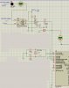
Project Description: Data Acquisition System for Solar Panel

In fact, i need to measure the current from solar panel and display it on the LCD.

I am using PIC16F877A with C language to do so. For the Temperature, Light, and Voltage, there is no issue of reading the sensors and it is working perfectly. However, ACS712 hall effect sensor is mentioned to be a good solution for DC current measurement in the datasheet as well as having a linearity characteristic, but the time i am using it with PIC, it does not give me a true value within at least 0-50 A input ranges.
This is the Proteus + ADC codes, Please help me to accomplish this task as well.


ADCON0=CHANNEL3;

lcd_goto(44);
read_adc();
current=read_temp();
current=0.074*current;
current=(current-37.888);
current=current/2;

dis_num(current);
send_char('.');
dis_num(current%10);

send_char(' ');
send_char('A');
send_char(' ');
 

Attachments

  • proteus.jpg
    proteus.jpg
    109.1 KB · Views: 6,010
You circuit shows a voltmeter across C6, does that read correctly?.

I'm a bit bemused about the circuit, what are the 4.7K, IN4148 and 10uF for? - all it will do is charge the 10uF, and you're then reading the stored charge on that, and not the current value.
 
The voltmeter across C6 is only to measure the voltage at that point. It helps to know the ratio of voltage change at the output of ACS712 to the input current.

ACS712 is a current sensor which only accepts Current (I) at the input and gives the analog voltage at the output. furthermore, this voltage is used along PIC to display the result of reading by some formula.

But the time the ratio of output voltage is not changing according to the input current. no fixed formula can be defined to give a true reading all the time or at least over a specific range of I values (lets say 0-50A).

4.7K is normally used to reduce the noise since this ACS712 is so sensitive towards noise.
1N4148 is for protection of PIC.

At last, i should say PIC only reads the voltage at the input and i don't think so that it is able to read current and do some processing based on that.(Based on my perception, maybe not true)
 
The voltmeter across C6 is only to measure the voltage at that point. It helps to know the ratio of voltage change at the output of ACS712 to the input current.

ACS712 is a current sensor which only accepts Current (I) at the input and gives the analog voltage at the output. furthermore, this voltage is used along PIC to display the result of reading by some formula.

But the time the ratio of output voltage is not changing according to the input current. no fixed formula can be defined to give a true reading all the time or at least over a specific range of I values (lets say 0-50A).

It won't change with that 10uF and diode there.

4.7K is normally used to reduce the noise since this ACS712 is so sensitive towards noise.
1N4148 is for protection of PIC.

How does it protect the PIC?.

It will certainly mess the readings up (as a minimum it's dropping them by 0.7V), and in conjunction with the capacitor it will only read the highest reading, and then nothing lower (until the capacitor discharges - and there's no discharge path).

At last, i should say PIC only reads the voltage at the input and i don't think so that it is able to read current and do some processing based on that.(Based on my perception, maybe not true)

Yes, a PIC (like anything else) measures voltages - to measure current you simply measure the voltage drop across a resistor (known as a shunt). To minimise voltage loss you would use a low value resistor, and an opamp to amplify the low voltage across the resistor.
 
Please refer to the datasheet of ACS712 (Page 12) applications. They also advice to connect diode and Capacitor. However just now i tried again to remove the mentioned components to see the difference, but still the same result i got.

May i know your advice about this particular application whether you prefer using of shunt resistor or current sensors like the one i am using?!
 
Please refer to the datasheet of ACS712 (Page 12) applications. They also advice to connect diode and Capacitor. However just now i tried again to remove the mentioned components to see the difference, but still the same result i got.

It also says "rectified output", so it's for an AC application, and it also says "C1 is a function of the load resistance and filtering desired.", so where did 10uF come from?, and what's your load resistance and required filtering?.
May i know your advice about this particular application whether you prefer using of shunt resistor or current sensors like the one i am using?!

The IC seems to provide it all internally, so should be fine, if connected correctly.
 
I have already removed it since this is for DC applications. I have no idea of the load resistance (I don't get what load you are talking about! the load which consumes power from solar panel?)Surely in this case the load resistance is considered to be so low, in order to have the least power loss . ( That's why i put a DIODE at the input of the current sensor). In fact without Diode, the current sensor is not working. Because in PROTEUS there is no DC current generator to connect at the input of ACS712.( That's why i applied voltage with a load-DIODE in series to have current).
 
I have already removed it since this is for DC applications. I have no idea of the load resistance (I don't get what load you are talking about! the load which consumes power from solar panel?)Surely in this case the load resistance is considered to be so low, in order to have the least power loss . ( That's why i put a DIODE at the input of the current sensor). In fact without Diode, the current sensor is not working. Because in PROTEUS there is no DC current generator to connect at the input of ACS712.( That's why i applied voltage with a load-DIODE in series to have current).

So you've not actually build the design?, so you don't really know if it works or not (except it won't as it's connected) - simulators are basically only playing computer games, it's not the real world.
 
I am going to build it soon. Proteus is a strong software and normally practically works when the simulation works.
 
Status
Not open for further replies.

Latest threads

Back
Top