Continue to Site

Welcome to our site!

Electro Tech is an online community (with over 170,000 members) who enjoy talking about and building electronic circuits, projects and gadgets. To participate you need to register. Registration is free. Click here to register now.

  • Welcome to our site! Electro Tech is an online community (with over 170,000 members) who enjoy talking about and building electronic circuits, projects and gadgets. To participate you need to register. Registration is free. Click here to register now.

MCP45HVX1 Digital POT and SH1106 OLED Display both on I2C

Status
Not open for further replies.

riccardo

Member
Hello,

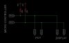
I am having a problem using an MCP45HVX1 digital pot and a common SH1106 OLED display together on the same bus.

Using an Arduino; If I talk to the display, sometimes the POT will glitch, and if I talk to the POT, the screen gets messed up.

Below is a simple sketch which should slowly turn up the pot resistance value, and display the value on the OLED display.

C:
#include <Arduino.h>
#include <U8g2lib.h>
#include <Wire.h>

U8G2_SH1106_128X64_NONAME_F_HW_I2C u8g2(U8G2_R0,  U8X8_PIN_NONE);
int value = 0;
char displayStr[25];    // Text output buffer

void setup(void) {
  u8g2.begin();
  u8g2.clearBuffer();
  u8g2.setFont(u8g2_font_5x8_tf);
 
  Wire.begin();
  pinMode(42, OUTPUT);
  digitalWrite(42, HIGH); // Connect Wiper
}

void loop(void) {

  sprintf(displayStr, " Value %i ", value);
  u8g2.drawStr(0, 8, displayStr); // Display Text: X(pixels[0-127]), Y(lines[0-7)
  u8g2.sendBuffer();          // transfer internal memory to the display

  delay(100);

  Wire.beginTransmission(0x3C); // transmit to POT_ADDRESS
  delayMicroseconds(10);
  Wire.write(0x00);           // Select wiper register
  delayMicroseconds(10);
  Wire.write(value);          // sends POT value bytes
  delayMicroseconds(10);
  Wire.endTransmission();         // stop transmitting
  value++;
  delay(100); 
}

As it is, the screen shows the incrementing number up until about 60 when it starts bouncing around and eventually becomes just a line and goes blank. THe POT resistance remains at the minimum apart from a few small glitches.

If i comment out the just POT related code, I get the same result.

If i comment out the just Screen related code, the pot resistance changes just fine, but occasionally the display will go all white, or staart flashing.

Apart from physically disconnecting one device from the bus while the other is written, Is there a wa to have these two items working together on the same bus?
 
In addition to the pull ups already mentioned, here are a couple of things to consider that might help, but I did not go through your code carefully.

First, you are leaving one check out, and that is the display without the dpot connected on the bus. You mention that screen problems continue when you comment out the dpot code, but you do not specifically state that the display works fine with the dpot removed. This is important to check explicitedly and to do so with repeated writing of 'value'.

Since it seems to be related to how many times you write value to the display (~60), I wonder whether you have the right constructor for your display. See the options here: https://github.com/olikraus/u8g2/wiki/u8g2setupcpp#constructor-reference

You are using:
U8G2_SH1106_128X64_NONAME_F_HW_I2C u8g2(U8G2_R0, U8X8_PIN_NONE);

Would another constructor like
U8G2_SH1106_128X64_NONAME_1_HW_I2C(rotation, [reset [, clock, data]]) (note buffer difference)
U8G2_SH1106_128X64_NONAME_1_2ND_HW_I2C(rotation, [reset]) make a difference? (note buffer difference) edited, that was for a secondary I2C address like on the ESP

When this bus interference has come up, it is supposed to be resolved by using one of the HW constructors [edit which you are using], see discussion here.

Do you know the I2C address of the display? Have you checked with a scanner? Also, do A0 and A1 need to be explicitly grounded or tied high?

I have used that type of display many times and with that driver with no problems at all.
Hope it helps
 
Last edited:
10k Pullups, bus to POT is 10mm, to OLED is 100mm cable.
The display works fine alone unless the code for the DigiPOT is still running
Same result with the other constructors
I2C scanner finds 0x3C (the POT)
Screen has the address 0x78 printed on the back

I think the problem is due to both devices seem to be accepting data that is not intended for them. I suspect some conflict between the screen library use of Wire, and the direct use I have for the POT but I am not really sure where to start.

I saw this post and tried calling Wire.End / begin between the display part and POT Part but this doesnt seem to help
 
+1 on scanner not finding the display.
Why not use a different library to isolate U8G2 issue.

Is it a selectable SPI and I2C interface? Can you post a pic front and back?
 
Does either device have an enable input, I know its using up arduino i/o, but if there is you could work around it using the enable.
 
Scanner doesn't find the display. If this the display does not ACK, could this be the issue, and is there a workaround?
It's I2C only.
Unfortunately no enable inputs
Display is this one
 
You can try using different pins for SCL and SDA and then use a SW constructor in U8g2.

Edit: To elaborate:
I am referring to this text from https://github.com/olikraus/u8g2/blob/master/doc/faq.txt:

Q: Why does my xxx_SW_I2C() device not work with my other I2C devices?

A: SW_I2C emulates I2C with digitalWrite(), which will have a conflict with other
I2C devices at the same pins. There are two options: (A) use xxx_HW_I2C() or
(B) use different pins with xxx_SW_I2C()


You are already using a HW constructor and it has not fixed the problem, Dedicating two different GPIO for the display only and a SW constructor might be the workaround.
 
Last edited:
Yes, this would probably solve the problem, but make me some new ones as software I2C is so slow. :D
Was hoping not to have to take that route :nailbiting:
 
Yes, this would probably solve the problem, but make me some new ones as software I2C is so slow. :D

It's VASTLY faster than your pot can be moved, so use software for the pot, and hardware for the LCD.

Not to mention the dual 100mS delays which make a mockery of any requirement for speed.
 
Scanner doesn't find the display. If this the display does not ACK, could this be the issue, and is there a workaround?
It's I2C only.
Unfortunately no enable inputs

If it had an enable input, then it wouldn't be I2C.

I've not used the multicolour version, but I have use both the 128x64 and 128x32 SSD1306 blue displays, and both ACK perfectly well.
 
Try flipping the I2C lines so that the data for one is the clock for the other and vise versa. That way you keep the same number of I/O's but avoid any communication collision.
 
Instead of both the POT and the DISPLAY sharing the same SCL and SDA lines, simply swap one of them. You will need to modify your code slightly to properly indicate which is the SDA or SCL.
 

Attachments

  • SCL_SDA_Swap.JPG
    SCL_SDA_Swap.JPG
    39.9 KB · Views: 232
Beau Schwabe I have never seen something like that ever. I just don't know how it could possibly work. I sincerely ask whether or not you have ever done that implementation, even bit banging, and had that work. I would be both amazed, stand corrected, tip my hat (if I wore one) and vow to start thinking further out of the box. I would also doubt my understanding of I2C (not that I think I am an expert in that area), and punish myself by having to re-read that Phillips pub and much more.

If you ask me, "why not"? My head will start hurting because I know that both I2C lines are bi-directional (ok, maybe without clock stretching, you could make SCL unidirectional) and I think you would have all sorts of problems. But, maybe I am wrong and that is why I am asking if you have ever successfully done that.

Nevertheless, I think that the *best* solution has already been offered and here is my reasoning, which I offer for critical review.

The OP is using a cheap display. There have been reports of problems with cheap displays not ACKing (see https://github.com/olikraus/u8g2/issues/192 for example, but just search for problems with SH1106 OLED .

I am assuming that the OP has such a display.
I am also assuming that the OP can not, or does not want, to write his own I2C routines.

Using a software definition for a separate set of pins will likely work, or at least should be tried. Yes, it will slow down the display - how important is that?? It was suggested that the dPOT could be used on a separate set of pins. I don't disagree, but that would mean writing his own I2C routines for the dPOT and not use wire.

Now, it is possible that my first assumption is wrong and that it is not simply that the display doesn't ACK (as someone mentioned, I too have used several SSD1306 OLEDs with I2c and multiple devices and never had a problem.

Look again at this exchange: https://github.com/olikraus/u8g2/issues/192 The OP there states, "The SSD1306/SH1106 controller supports two I2C addresses (0x3C/0x3D [or 0x78/0x7A as marked on the generic Chinese displays]), with 0x3C/0x78 being the default.."

Remember, the OP has stated that the scanner finds the dPOT at 0x3c and he has also stated that the display is marked as using 0x78.
The author of the display library has posted here https://github.com/olikraus/u8g2/wiki/u8g2reference#seti2caddress ...

That U8G2 uses the LOWEST display address by default and this would cause a conflict with the dPOT. There is a remedy, however, see https://github.com/olikraus/u8g2/wiki/u8g2reference#seti2caddress by using void u8g2_SetI2CAddress(u8g2_t *u8g2, uint8_t adr)

Alternatively, the dPOT address can be easily changed.

That's how I see it anyways.
 
Why not use a good old analogue pot.

Mike.
Edit, I see it's being used as output. Maybe PWM with resistor cap combo.
 
Beau Schwabe I have never seen something like that ever. I just don't know how it could possibly work. I sincerely ask whether or not you have ever done that implementation, even bit banging, and had that work.

When I worked at Parallax Inc, this method was used to instantaneously expand an I2C buss with an 8-device address selectable limitation allowing for 16 devices. This method has been tested and proven. Over the years I have run into "some" I2C devices that do not communicate well on the same buss. Using this trick if you have the program capability to assign I2C pins would usually solve the problem.
 
When I worked at Parallax Inc, this method was used to instantaneously expand an I2C buss with an 8-device address selectable limitation allowing for 16 devices. This method has been tested and proven. Over the years I have run into "some" I2C devices that do not communicate well on the same buss. Using this trick if you have the program capability to assign I2C pins would usually solve the problem.

I'll take your word on it...but if you (or anyone else) recall a cite, I would love to know. Hey, I learn new things all the time. Personally, no, I'm going to stick to using it the way it is supposed to be used...so far that has worked ok for me.
 
Status
Not open for further replies.

Latest threads

New Articles From Microcontroller Tips

Back
Top