Electro Tech is an online community (with over 170,000 members) who enjoy talking about and building electronic circuits, projects and gadgets. To participate you need to register. Registration is free. Click here to register now.
Welcome to our site! Electro Tech is an online community (with over 170,000 members) who enjoy talking about and building electronic circuits, projects and gadgets. To participate you need to register. Registration is free. Click here to register now.
hello guys. I am Timothy. i have been working on Rs232 and serial communication for a while now. the major issue in the circuit is the max232 I.C . i have observed all rules in its connections, still not working. please help out.
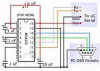
In this example I did "Print Screen" then copied to paint. Then selected part of the picture and "Control-C" to copy to this Post.
This part is a little grumpy about where and how the capacitors are placed. C1, C2, C3, C4, C5.
Do you have 10V on Pin 2? and -10V on Pin 6?
----edited----
It is common go get mixed up on "in" and "out", on the micro and on the RS232 part.
"TEST" What do you have? Meter, Scope, Logic Probe? LED and Resistor?
First check the +-ve 10v and see if both present, you could next try taking the TTL inputs hi & low and see of the RS232 swings from + & - v.
Do the same with the RS232 inputs taken to + & - 10v and see if the TTL out puts swing 0 to 5v
Max.
just seeing this now. Thanks Ronsimpton and MaxHeadRoom78 . i will do as you have said and bring back the result
want to ask, what is the values of the capacitors. i used 10 uf.
I can see nothing wrong with your schematic. I think it should work with the 10uF capacitors. (make sure that the polarity of the capacitors is correct.) You need to post the results of the tests that Max suggested in post #6. If you do not get +10V on pin 2 and - 10V on pin 6 we need to first find out why first.
I agree Max. I have just had a look at things I have built using MAX232s. I have used 10 uf in one and 22 uF capacitors in the other.
I now use ST232s which only need 0.1 uF (100 nF) capacitors. They are also cheaper.
I am not going to comment any more until we know the voltage on the pins I marked in red.
For pins 13 & 14 they should be measured with and with out the DB9 plugged in.
Compliment of the season guys.
Thanks for all you effort and comments. i do appreciate.
I have gotten the solution to the problem.
The problem was with the serial to USB converter cable. i changed it by instinct , and the project started working properly.
But what surprises me is that the computer never gave any error about the cable. is there any way of testing if a serial to USB converter cable is working properly ?
Plug the USB in to the computer.
On the serial end connect RX and TX together.
Send out a character and you should get the same thing back. (or send out a short string)
By send; Send to USB from PC.
Hello guys. I have a question.
I am trying to interface my microcontroller to a GSM modem.
The GSM module am using is SIMCOM908.
do I still need the max232 in between the microcontroller and the GSM module ?
Hello guys. I have a question.
I am trying to interface my microcontroller to a GSM modem.
The GSM module am using is SIMCOM908.
do I still need the max232 in between the microcontroller and the GSM module ?
Almost certainly not, and doing so could well damage it - unless of course the module already includes a MAX232 in order to directly feed a PC serial port.
Using a MAX232 would probably also stop it working, as it inverts the signals.
This site uses cookies to help personalise content, tailor your experience and to keep you logged in if you register.
By continuing to use this site, you are consenting to our use of cookies.