Continue to Site

Welcome to our site!

Electro Tech is an online community (with over 170,000 members) who enjoy talking about and building electronic circuits, projects and gadgets. To participate you need to register. Registration is free. Click here to register now.

  • Welcome to our site! Electro Tech is an online community (with over 170,000 members) who enjoy talking about and building electronic circuits, projects and gadgets. To participate you need to register. Registration is free. Click here to register now.

Manual for Cossor 4100 Oscilloscope.

Status
Not open for further replies.

Hero999

Banned
I don't need the full service manual although it would be nice.

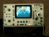
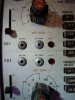
All I'm after is the user manual or at least a general specification. I would like to know the bandwidth, power consumption, slew rate, maximum input voltage etc. and any features I haven't yet managed to figure out.:D

It also needs calibrating so I'd like to know how to do that.

Thanks in advance.
 
Last edited:
No one knows?

Here's a picture, sorry if it's not very good.

One thing I've noticed is that the beam occasionally jitters up and down randomly. I don't know if this is a fault with the scope, noise or just vibration.

Apart from that, it works perfectly.
 

Attachments

  • Scope.JPG
    Scope.JPG
    1.4 MB · Views: 958
I've discovered that this scope is out of calibration.

There are some calibration controls on the front and side panels.

I take it that I need to remove the hex head screws before I adjust the pots underneath or are the hex heads connected directly to the pots?

What does A CAL and B CAL mean?

Is that the timebase calibration an why A and B?
 

Attachments

  • ScopeCal1.JPG
    ScopeCal1.JPG
    1.6 MB · Views: 537
  • ScopeCal2.JPG
    ScopeCal2.JPG
    1.7 MB · Views: 440
  • ScopeCal3.JPG
    ScopeCal3.JPG
    22.4 KB · Views: 422
Does know one know the answer or is it that not many people check this section?

Here are some better pictures.

I've managed to calibrate the gain of channel 1 and 2 and the timebase.

I worked out that A is the timebase.

What's B for?

What does ACF and ACS mean?
 

Attachments

  • Scope2.JPG
    Scope2.JPG
    1.7 MB · Views: 536
  • ScopeCal4.JPG
    ScopeCal4.JPG
    1.7 MB · Views: 487
  • ScopeCal5.JPG
    ScopeCal5.JPG
    1.6 MB · Views: 802
Does know one know the answer or is it that not many people check this section?

Probably (like me) no one has seen a Cossor scops for decades.

Here are some better pictures.

I've managed to calibrate the gain of channel 1 and 2 and the timebase.

I worked out that A is the timebase.

Only the main timebase.

What's B for?

The second timebase, it's a dual timebase scope.

What does ACF and ACS mean?

AC-Fast and AC-Slow?.
 
Thanks for the reply.

I've noticed another setting: S/S do you know what it does?

How would I used the dual timebase function?

I haven't used a scope that does that.
 
Presumably Single Scan?.

The dual timebase allows you to zoom in on part of the waveform you're examining, so you have one trace displaying the full waveform, and the other displaying a zoomed in portion of that waveform.
 
I've figured out how to use the dual timebase function or at least I think I have. :D

Single scan does what it says on the tin, after it's triggered the scope will scan once and won't trigger again until the reset function is activated.

I still don't know what AC-Fast and AC-Slow means; is it different rise time of cut-off frequencies?
 
I've figured out how to use the dual timebase function or at least I think I have. :D

Single scan does what it says on the tin, after it's triggered the scope will scan once and won't trigger again until the reset function is activated.

That's correct - but do you know why it's there?.

I still don't know what AC-Fast and AC-Slow means; is it different rise time of cut-off frequencies?

It's filtering on the sync signal - if you're trying to sync a video signal you have a low frequency (frame) and a high frequency (line) - you use this to sync either high or low.
 
That's correct - but do you know why it's there?.
No, it seems a little pointless as it isn't a storage scope, the scope if triggered, you see one scan which normally over in the blink of an eye.
 
No, it seems a little pointless as it isn't a storage scope, the scope if triggered, you see one scan which normally over in the blink of an eye.

It's for taking a photograph of the screen - you use a special camera that locks over the front of the tube, open it's shutter, then do the single sweep to expose the film.
 
I wonder if I could do it with a digital camera.

I could film it, using the video function, then merge all the fames together. Assuming I could find a program that can do the merge of course.

I suppose this is only good for low frequency waveforms anyway.
 
Cossor 4100

I attach the specification for the Cossor 4100 oscilloscope. About 1978. It was probably the most modern Cossor scope that one ever sees. High performance, and fairly sophisticated. The manual is difficult to work with, like most Cossor manuals, very much aimed to show each circuit board, with switch connections and associated circuits on another page, so it is not easy to trace circuit operation through. Bill m0wpn
 

Attachments

  • Cossor4100cat.pdf
    659.6 KB · Views: 587
Great, thank you very much.

If you have any more information then please post it.

Thanks again.

EDIT:
Going by this, the 'scope is much better than I originality thought, far superiour to my old Tektronix 10MHz scope (can't remember the model number, I'll post it if you're interested).
 
Last edited:
The scale back light has now stopped working.

I assume the bulb has just gone, could it be anything else?

Is it easy to replace?

Here's a picture of it before the bulb blew. I take it the bulb is at the top?

https://www.electro-tech-online.com/attachments/9v-1ms-better-jpg.31336/

If it's too hard to replace then I won't bother but it would be nice. Ideally I'd replace it with LEDs to prevent this from happening again.
 
Here's a picture of the back of the CRT.

I don't think those connections a for the backlight though. The voltage between the two wires was 35V regardless of the birghtness setting. I acidentally shorted one to the chassis, it sparked and make a loud pop which sounded like a a small capacitor being shorted and left a black mark where it had shorted. Fortunately no real damage was done and the 'scope still works.
 

Attachments

  • Backlight.JPG
    Backlight.JPG
    1.6 MB · Views: 494
I've noticed another thing: on some settings I can see another waveform of a lower frequency superimposed on the main one. This is more noticeable at lower intensity and faster timebase settings.

Is it the retrace?

I've not noticed this with other 'scopes, many of them with a lower bandwidth and poorer specification.

Is there away to eliminate this?

Sometimes I need to use lower intensity settings so I can photograph it with my digital camera so just turning the brightness up is not the answer.
 

Attachments

  • retrace1.JPG
    retrace1.JPG
    1.6 MB · Views: 1,002
  • retrace2.JPG
    retrace2.JPG
    1.6 MB · Views: 526
How would this be normally done?

Is it just a case of recalibration or does it need to be repaired?
 
Status
Not open for further replies.

Latest threads

New Articles From Microcontroller Tips

Back
Top