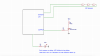
The following simple diagram shows a concept which I'll try to execute in near future. Since I am new to Arduino, I'd appreciate any help. The alarm is mainly used for several window and door contacts (normally closed) in series. It will activate upon opening of any contact. The problem that I've had with previous circuits based on simple logic gates was the false alarm. I don't what was the source but my best guess is RFI noise due to long wire etc. By using Arduino I should be able to make more intelligent system which needs to meet some conditions before it can activate the alarm.
1. At the start all outputs are low. The power on delay starts and continue for 5 min. This is indicated by a LED. If any of the contacts are faulty i.e. open contact, the system won't proceed and the LED will be off.
2. After 5 min exit delay period, sensors I/O (analogue out/in) sends a current through wire and sensors. The sensor input pin also has low pass filter ,10K/0.01uF (not shown) to block RFI noises. The system goes into standby mode. I am going to use one of the sleep libraries to minimise the current consumption.
3. When any of contacts opens, the system won't react immediately, it waits 100ms and read again, repeat for three times. If the input pin reading is still lower than predetermined threshold voltage, the system then would react and sound the alarm. Any false alarm due to external noises shouldn't cause issue anymore.
Please let me know what do you thing and if you have any suggestions to further improve. Help with coding is also greatly appreciated.
Attachments
Last edited:
