Continue to Site

Welcome to our site!

Electro Tech is an online community (with over 170,000 members) who enjoy talking about and building electronic circuits, projects and gadgets. To participate you need to register. Registration is free. Click here to register now.

  • Welcome to our site! Electro Tech is an online community (with over 170,000 members) who enjoy talking about and building electronic circuits, projects and gadgets. To participate you need to register. Registration is free. Click here to register now.

Making a cheap microphone with a simple preamp circuit.

Status
Not open for further replies.
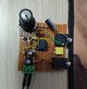
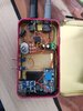
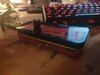
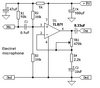
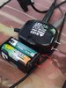
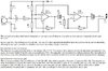
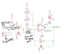
I put the whole thing in a box (the circuit in the last photo I sent). Made a switch for disabling the bias resistor, now I am using it with a dynamic mic and works amazingly well. Only problem is powering it up. Anything that is connected to wall introduces interference to the circuit so I am stuck with these 4 AAs for now. Can I power it up from USB power without those annoying frequencies invading the circuit. For amplification values more than 100 I heard a two op amp solution is better because of bandwidth issues. How much that would effect me if I wanted to get 200 times gain instead of 100 from the this circuit. I found this diagram but when I built it on breadboard it had very bad high frequency noise. audioguru
 

Attachments

  • IMG_20210422_140022.jpg
    IMG_20210422_140022.jpg
    1.2 MB · Views: 289
  • electret-microphone-pre-amp.jpg
    electret-microphone-pre-amp.jpg
    81.8 KB · Views: 377
Last edited:
Well there's a complete lack of any decoupling capacitors in that circuit, so it's not going to work very well - and batteries won't last that long either because of it.

There's even a 'sticky' at the top of this very forum:


But if you want to keep your existing circuit you need decoupling across the main supply (capacitor), on the artificial spilt supply (capacitor), and on the bias to the electret (resistor and capacitor). These are fundamental essential components in such a circuit, battery powered or not.
This is the current circuit in the box. I will definitely check the link.
 

Attachments

  • Screenshot_13.png
    Screenshot_13.png
    130.2 KB · Views: 547
Your 5532 opamp has a minimum allowed supply of 6V but your Ni-MH batteries drop to only 4.0V and your 5V noisy power supply is also too low.
Your low resistor values are reducing the mic output level.
 

Attachments

  • corrected mic preamp.png
    corrected mic preamp.png
    72.3 KB · Views: 536
Your 5532 opamp has a minimum allowed supply of 6V but your Ni-MH batteries drop to only 4.0V and your 5V noisy power supply is also too low.
Your low resistor values are reducing the mic output level.
Oh, so missing RC filter is the problem that causes everything other than a battery introducing a hissing sound. I actually have a 47uF capacitor across positive and negative therminals. So I need a RC filter and a capacitor across R4 (R6 in your example) as Nigel said. What values are suitable for the RC filter. By the way my NE5532P variant claims to have an low minimum input voltage of 3.5V, I tried 4 alcaline batteries to get 6V but the difference in noise was unnoticable. I coudnt use a boost converter because I could hear the operating frequency of the boost converter invading the circuit. It consumes 2 ma at 6 volts. Why do I need a capacitor at the pin 1, output pin. Some examples does not include that.
 
Last edited:
An old style of power supply makes a low frequency hum sound when decoupling capacitors are missing in a preamp circuit. But now you describe the sound and say it is a high frequency hiss. Then your power supply is not an old style that makes hum, instead it is a new small style (like a boost converter) that makes hiss. Decoupling capacitors in your circuit should reduce the hiss.

The low value capacitor parallel with the negative feedback resistor reduces high frequency gain which reduces hiss, high frequency consonants in voices and reduces high frequencies in music.

All forms of the old NE5532 dual opamp have a minimum supply of 6V. A lower voltage does not cause hiss, instead it causes distortion.
 

Attachments

  • 5532 opamp.png
    5532 opamp.png
    18.4 KB · Views: 223
An old style of power supply makes a low frequency hum sound when decoupling capacitors are missing in a preamp circuit. But now you describe the sound and say it is a high frequency hiss. Then your power supply is not an old style that makes hum, instead it is a new small style (like a boost converter) that makes hiss. Decoupling capacitors in your circuit should reduce the hiss.

The low value capacitor parallel with the negative feedback resistor reduces high frequency gain which reduces hiss, high frequency consonants in voices and reduces high frequencies in music.

All forms of the old NE5532 dual opamp have a minimum supply of 6V. A lower voltage does not cause hiss, instead it causes distortion.
Maybe I saw a wrong schematic, I coudn't find the 3.5V mentioned later. Do you have a schematic suitable for dynamic microphones with gain up to 200, I guess I will build another circuit from scratch since this one is hot glued to the plastic and adding stuff would be too difficult anyway. I actually found 10 brand new NE5532 chips laying around in my house because some aliexpress seller sent them instead of NE555 chips like 2 year ago :D 
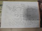
While building one from scratch I want to add bass and tremble control but it seems to complicate thing too much so I may not. Can I change the TL071 in the pinned "excellent electret mic preamp" circuit Nigel Goodwin posted with NE5532 it looks like I only need to change 7 pin to 8 and 6 to 1 but I don't know the different characteristics of both op amps and I don't have the knowledge to fully understand a schematic and modify a circuit. I guess they will not teach us in collage until the 3th year. I know there are multiple schematics on the internet but most of them lack the decoupling capacitors or has other problems as you mentioned.
 
Sorry I asked everything from you which is extremely lazy, instead I will try to learn it myself, the corrected circtuit you sent only contains first amplifier so I am assuming I don't need two of them the get 200 times gain. I will change the 10K resistor with 5K and 100K with 1M potansiometer connected series with 100K resistor. So from my current understanding it will have 1.1M/5K+600ohm = ~196 times gain adjustable down to ~18 times since my dynamic microphone has a 600 ohm impedance. I did put a switch between bias resistor and microphone to make it work with both dynamic and electret microphones in my first circuit. I will research more about it to find the other values of maybe change both of the resistor value to something smaller. If you ask why I switched to a dynamic from electret, it is because I got a good deal on one and I like the single direction characteristic of it over the omi directional electret microphone.
 
Your preamp uses inverting opamps with low value resistors then its NE5532 dual opamp IC is used. Nigel posted the electret mic preamp that I designed and it uses R1 to power the Jfet in an electret mic. R1 should be removed if a dynamic mic (coil and magnet) is used.

The TL071 is a single opamp but the NE5532 is a dual with 2 opamps in it so look at the datasheets to get the proper pins.
I just made the same circuit after getting a TL071. Only difference is 500k pot and used 2X 1K resistors in series instead of the 2.2K so it should have 250 times gain. Much cleaner audio when I compare it with the first one. I will put it in a metal case with a battery soon.
 

Attachments

  • IMG_20210430_023929.jpg
    IMG_20210430_023929.jpg
    2.4 MB · Views: 209
  • IMG_20210430_023950.jpg
    IMG_20210430_023950.jpg
    5.3 MB · Views: 200
Still got some fluctuating noise from the boost converter, tried multiple things but nothing except adding a 100ohm resistor series to supply power helped (that resistor fixed the startup noise issue due to the capacitor charging too fast). I tried the inductive divider in this site **broken link removed** but nothing really changed. I also added a 100uF capacitor in the input terminals of the converter and 10p capacitor between 6. and 2. pins to reduce high frequency gain. It is much better than the first circuit I built. First one wasn't even usable with boost converter due to the noise. Can we modify the RC filter in your circuit to get better performance with the boost converter,
 

Attachments

  • IMG_20210430_162801.jpg
    IMG_20210430_162801.jpg
    4.9 MB · Views: 228
  • IMG_20210430_161556.jpg
    IMG_20210430_161556.jpg
    1.6 MB · Views: 244
  • 16198199105742793340214783462943.jpg
    16198199105742793340214783462943.jpg
    5.4 MB · Views: 225
  • Electret mic &#1.PNG
    Electret mic &#1.PNG
    5.1 KB · Views: 248
Last edited:
My electret mic preamp circuit does not have a high frequency filter, instead it lets the TL071 opamp produce a flat frequency response to 30kHz then and when its gain is 200 then it has a natural rolloff of high frequencies that drops at 6dB per octave.

Why charge a battery then use a boost converter to power the preamp with noise? Instead use the boost converter to charge a "9V" Ni-MH battery that can be used for a few long days for each overnight charge.
I see, I really need a 9V rechargeable battery in this thing, I just don't have one. It would make thing so much easier. Now I feel like a idiot for wasting so many hours on it.
 
My electret mic preamp circuit does not have a high frequency filter, instead it lets the TL071 opamp produce a flat frequency response to 30kHz then and when its gain is 200 then it has a natural rolloff of high frequencies that drops at 6dB per octave.

Why charge a battery then use a boost converter to power the preamp with noise? Instead use the boost converter to charge a "9V" Ni-MH battery that can be used for a few long days for each overnight charge.
I eliminated the boost converter noise but the high gain noise is pretty audible so I looked for a op amp with lower noise. Only one I could find was NE5534, it has same pinouts but it didn't really worked when I swapped it with TL071. I bought it from a respectable seller so I don't thing it is a fake one, why do you thing it didn't worked. It only creates noise which increases when I increase the gain but no actual sound.

Ok I found out the high frequency noise was coming from my sound card when its sensitivity is maxed. So after setting the computer setting to 90/100 from 100/100 and increasing the gain from the preamplifier it sounds much better. Replacing the op amp was unnecessary but I still wonder why 5534 didn't work.
 
Last edited:
Use the offset pins. See image below from TI datasheet.

The 6v supply means you have a maximum output voltage swing of +/-1.75v (3.5v)

B8C946AC-1B42-4379-A087-811A040CBDE0.jpeg
 
Use the offset pins. See image below from TI datasheet.

The 6v supply means you have a maximum output voltage swing of +/-1.75v (3.5v)

View attachment 131485
I use it with 15V with a boost converter. I saw the NE5534 as a direct replacement in a forum, I have no intensions of changing the circuit. Since the noise dropped a lot after the tweak I done with the computer settings I don't need to change the op amp. But if there is a direct replacement op amp with better specs I might consider it.
 
OPA134 single, OPA2134 dual and OPA4134 quad opamps are excellent for audio and their minimum supply is 5V.
 
OPA134 single, OPA2134 dual and OPA4134 quad opamps are excellent for audio and their minimum supply is 5V.
I got a opa134pa. It was quite expensive for a 8 pin IC. Anyway completely same issue happened I had with the 5534. It didn't work, only a faint noise that increases with the gain but no actual voice. It only works with the TL071 for some reason. I checked the pinouts there should be no problem there. Should I just leave as it is, sometimes human logic don't work with electronics I assume.
 
My electret mic preamp circuit does not have a high frequency filter, instead it lets the TL071 opamp produce a flat frequency response to 30kHz then and when its gain is 200 then it has a natural rolloff of high frequencies that drops at 6dB per octave.

Why charge a battery then use a boost converter to power the preamp with noise? Instead use the boost converter to charge a "9V" Ni-MH battery that can be used for a few long days for each overnight charge.
Hi, I have a question about your high frequency rolloff calculation. The gain bandwidth product of TL07x op amps is 5.25Mhz. Our Prof. made us use 3 cascaded stages of LM741s with 5 gain at each stage to have a gain of 125 while having enough gain to cover human hearing limits for making a AM radio. Which makes sense since 4Mhz (the gain bandwidth product of LM741) divided with 5 makes 20Khz. So TL071 should not be able to have enough gain at 200 times gain which makes me question if my calculation is wrong since your circuit works perfectly. I also failed to find a graph for gain vs. bandwidth for both op amps.

Also I had this problem at lab. The 3 stages of op amps never gave me the calculated gain I needed. Instead middle stage got stuck around 2 times gain no matter the value of feedback resistor and output clipped around 1.5V while they were supplied with +/-15V DC. I was not only one who suffered from this problem and I couldn't find a way around it.
 

Attachments

  • 1651863318631.jpg
    1651863318631.jpg
    5.7 MB · Views: 178
Status
Not open for further replies.

Latest threads

New Articles From Microcontroller Tips

Back
Top