Fluffyboii
Active Member
Hi, my usual headphones died recently and I had to send it to warranty. So I was looking for a microphone. First I tried using my earphones built in microphone and got a cable to split the audio cable to mic and speaker which worked but the volume was unacceptably low. So I got a cheap condenser desk microphone for 5 bucks and It sounded ok, still low volume.
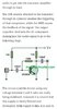
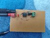
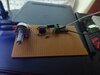
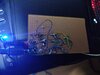
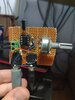
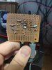
My interest in building one spiked for some reason I got a MAX9814 board with AGC from overseas but It will take over a month to arrive. So I put together the simple single transistor pre amp with the parts I had laying around. And It worked. I was so sure that it will not work but it works surprisingly well. Anyway I made some changes on it, tried some different values. It consumes around 5ma with 12 volts and less than 3ma with 9 volts so It should last forever with a single 9V battery. I am currently using 4 AAs because I hate 9V batteries. The original schematic is below.
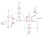
I purchased some tantalum capacitors for better audio quality and 4 electret microphones for experimenting with. I also ordered necessary parts for other circuit I found from GreatScotts channel. It has probably better audio with less noise since it got high and low pass filters and an amp IC. I will also try to build that one to see how it performs.
I got multiple questions about amplifiers though:
Since electret mics are condenser ones it should be ok to connect them in parallel configuration but what about series. They have transistors built in so I assume series connection is pointless, but it would be good if I could get a 2 parallel 2 series connection for better quality. İf I connect 4 of them in parallel would I need to adjust the 10Kohm resistor to something with quarter value to get the same amount current to all of the individual mics.
Can I use more than one transistor to amplify the output even more. I dont remember the name of that configuration but I know connecting multiple transitors in a spesific manner can make a amplifier. Although I am sure that it would increase the noise even more.
Can these preamp circuits applied to dynamic or ribbon microphones. I guess I need to remove the voltage connection to the mic itself for that to work.
Can I get a big condenser capsule and make it work without a phantom power with a simple power supply.
When I try to feed the single transistor preamp with any electricity source other than batteries it gets intense interference, using power adapter was impossible because of that and also USB power from pc was quite noisy. I tried using a linear voltage regulator with lots of filtering but it didn't effect the outcome.
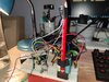
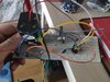
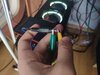
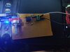
Also I don't understand how should I connect jack wires. I will sent a picture of the current setup which is connected to only at the right channel but I guess it is ok since it is mono.
I want to learn more about microphones and preamplifier circuits. I will solder all of these on perfboard when I settle with a good circuit and got the jack connectors with other stuff.
My interest in building one spiked for some reason
I got a MAX9814 board with AGC from overseas but It will take over a month to arrive. So I put together the simple single transistor pre amp with the parts I had laying around. And It worked. I was so sure that it will not work but it works surprisingly well. Anyway I made some changes on it, tried some different values. It consumes around 5ma with 12 volts and less than 3ma with 9 volts so It should last forever with a single 9V battery. I am currently using 4 AAs because I hate 9V batteries. The original schematic is below.I purchased some tantalum capacitors for better audio quality and 4 electret microphones for experimenting with. I also ordered necessary parts for other circuit I found from GreatScotts channel. It has probably better audio with less noise since it got high and low pass filters and an amp IC. I will also try to build that one to see how it performs.
I got multiple questions about amplifiers though:
Since electret mics are condenser ones it should be ok to connect them in parallel configuration but what about series. They have transistors built in so I assume series connection is pointless, but it would be good if I could get a 2 parallel 2 series connection for better quality. İf I connect 4 of them in parallel would I need to adjust the 10Kohm resistor to something with quarter value to get the same amount current to all of the individual mics.
Can I use more than one transistor to amplify the output even more. I dont remember the name of that configuration but I know connecting multiple transitors in a spesific manner can make a amplifier. Although I am sure that it would increase the noise even more.
Can these preamp circuits applied to dynamic or ribbon microphones. I guess I need to remove the voltage connection to the mic itself for that to work.
Can I get a big condenser capsule and make it work without a phantom power with a simple power supply.
When I try to feed the single transistor preamp with any electricity source other than batteries it gets intense interference, using power adapter was impossible because of that and also USB power from pc was quite noisy. I tried using a linear voltage regulator with lots of filtering but it didn't effect the outcome.
Also I don't understand how should I connect jack wires. I will sent a picture of the current setup which is connected to only at the right channel but I guess it is ok since it is mono.
I want to learn more about microphones and preamplifier circuits. I will solder all of these on perfboard when I settle with a good circuit and got the jack connectors with other stuff.