Continue to Site

Welcome to our site!

Electro Tech is an online community (with over 170,000 members) who enjoy talking about and building electronic circuits, projects and gadgets. To participate you need to register. Registration is free. Click here to register now.

  • Welcome to our site! Electro Tech is an online community (with over 170,000 members) who enjoy talking about and building electronic circuits, projects and gadgets. To participate you need to register. Registration is free. Click here to register now.

Making a 50a+ buck converter.. maybe

Status
Not open for further replies.
Hey guys.
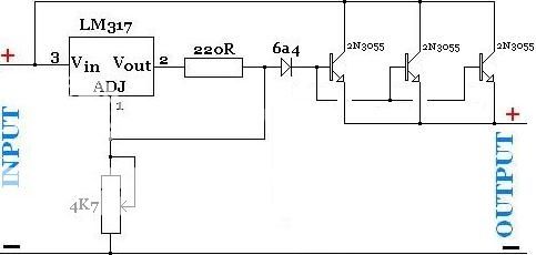
For a new project I want to control a 8.4v dc source to output 1-~6v 50a or more to a load that, at its minimum, will be ~.04 ohms..
I've got a basic buck convertor diagram that I think will work but I'm grossly lacking in specifics when it comes to actually building it. If I'm honest there's very little chance I could work out any of this myself :( .. but I'm great at following directions :);)
I've got a 50mm×80mm×10mm footprint to fit this into, I could vary that a little but that'd be the ideal size.


SMPS-transistor-on_zpsrbf6inuh.gif


50a or more would require multiple capacitors I guess? what do I need there?
The transistor and diode, where do I find 50+a examples of those?
The transistor needs a pwm square wave driver circuit, and just so I've got this right, it being adjustable via pot is how the voltage is regulated right?
And the last specific I'm missing.. how the hell do I work out the inductor :nailbiting:
I guess it'll need some pretty thick copper wire to cope with the load, (probably the only thing I can work out), but I've no idea of how long the wire should be, the diamiter of the coil, the composition of the core it wraps around or how I'd aquire/fabricate said core.

As always, any help here would be greatly appreciated.
 
Technically doable but not realistically DIY level doable (unless you are extremely well versed and production capable in SMPS design) given the small space constraints. :(
 
Not sure, but I think you're trying to make it harder than it is, here's a circuit I use with some success to power an 18 volt sawsall from 12-14 volt in my offroad vehicle. It fails to maintain 18 when too heavily loaded, but it works. I ordered the inductor from Wurth and I've had the 21.5 millifarad, 40 volt cap for over 20 years.
 

Attachments

  • RYOBI SAW POWER.asc
    4.9 KB · Views: 174
  • ryo.JPG
    ryo.JPG
    116.7 KB · Views: 2,123
Sorry - Kinarfi's curcuit is a boost (step-up); the OP is looking for a buck (step-down) circuit.
The circuit in #1 is the right topology, but it is only conceptual - it's a long way from being a complete circuit. I tend to agree with TCM - the space constraint is going to make and already challenging circuit very difficult indeed.
 
I did something like this for the Mrs, she does pyrography, standard tips use 2v at about 30 amps.
In the end I found a 2v regulator out of an old server and used it.
However before that I was thinking of using an electronic lighting transformer, you can get them cheap, they have about 10 turns on a ferrite ring for the secondary, reducing that to 1 or 2 would give you something on the lines of that voltage.
 
I've found a few 50a inductors on ebay, though I don't yet know how the mH, uh and % values that they're assigned affects the circuit. I've read I can swap the transistor and diode for mosfets so sourcing 50a capible ones should be easy, though I've no idea how to time the gate pulses. Still no clue what capacitors to use.. actually reading more about the topic highlights how much I don't yet understand (and just how bad my math actually is haha). I'm sure I'll get there, just not any time soon without copious assistance :( I'll revisit the idea when I've a better grasp of it.

So, aside from a buck converter, is there another more simple, diy friendly (borderline steampunk will do:p) way to make an ajusible voltage controller with suitable current capability and size?
 
Hi,

Start with a 1 amp converter and work your way up. You should probably get that working perfectly before going to the 50 amp'er.

A 50 amp buck will require an inductor that can handle a peak current greater than that. The diode has to handle more than 50 amps, so does the transistor.

The peak current is of prime interest. That determines what kind of caps you need too. They have to have a rating that can handle the expected RMS current.

The inductor size determins the peak current and thus also plays a part with the cap in the output ripple voltage. The ripply voltage is often a target concern also because you dont want too much ripple in most cases, unless you are doing something that dosent matter as much like a battery charger.

So you have low ESR inductor, low ESR caps and can handle the expected RMS current, a fast diode like a Schottkey that can handle maybe 25 percent more current than the rated output (that brings it up to over 60 amps), transistor has to handle the peak current.
If there is no slow start than you have to make sure the transistor can handle the initial surge current which might make it's way up pretty high, which means you should have a slow start mechanism also. Without that even a 100 amp transistor could blow out, although it does depend on some other things too like the input source impedance, which we dont know what it is yet.

So your main concerns are in terms of voltage and current ratings, and you have to know what the peak current is which means you have to calculate that. A typical method is to assume a 50 percent duty cycle and go from there.
 
You haven't stated what this is for so it's hard to give alternative ideas. If it is similar to a pyrography heater then simply PWMing the 8.4V will give the required result.

Mike.
 
Mr Al's right a 50a inverter isnt a noob project, start by building a couple of smaller ones.
Take it from someone who's built and blown up plenty of prototypes, inverters are not that easy.
 
https://www.ebay.com/itm/100W-12A-D...678499?hash=item258a18e9e3:g:c5gAAOxyLN9SfFrs
I hope this link works. I searched ebay for "DC-DC Buck Step Down". There are 1A, 2A, 5A and some (about) 10A versions.
I know this does not get you to 50A but I think you can parallel 5 of these.
By the questions you ask; you should not start out at 50A. If you want to start out at 1A; that we could try. I think your best bet is to get one all put together and working.
 
Non taken. Well, maybe some haha.

The buck converter topology I found at the beginning of this thread seemed, at the time, the most simple way of high current voltage control. So much reading been done since then and now and I'm pretty sure it's a good solution but as you fine folk pointed out, its not a complete circuit and certainly not for a diy beginner to make so. I will follow up on it at a later date after some experimenting with lower currents.. but until then, I found this voltage regulator schematic
adjustable-very-high-power-supply-with-lm317-voltage-regulator_zpsdgajfkpj.jpg
(http://www.reuk.co.uk/wordpress/electric-circuit/high-current-voltage-regulation/)
There's also few more schematics on the page. This type of circuit will fit my criteria right? If so, can anyone show me the most efficient one please.
 
Hi,

Well that is a linear circuit, and though it will work to some degree you should be aware of the pitfalls.

First, the LM317 requires maybe about 2v across it for normal operation, so the output at pin 2 will be 2v lower than at 3v, which means for a 5v output you need a 7v input, and the diode drops about 0.7v so that's another drop, then the base emitters of each transistor drop another 0.7v roughly, so that's a total drop across each transistor collector emitter of 2+0.7+0.7=3.4 volts, which at 50 amps means 170 watts. That happens to be best case however, as the power goes up as the input voltage goes up if the output voltage stays the same. So with 5v output and 10v input, we have 250 watts lost in the regulator. This is why buck circuits were invented :)

It's up to you if you want to try it that way, but you'll need big heat sinks for one.

Maybe looking into the parallel connection of several 10 amp buck's would not be a bad idea as someone suggested already.

For what it is worth, i was looking into building a buck circuit that could do i think it was 30 amps and i found that the inductor would be too expensive and for my app i could not use parallel run of the mill bucks because i was going to have something like a 120vdc input buss with only 12v output.

There's also the variac approach. You use a variac to adjust the input to the linear (with rectifier of course) and that way you dont loose as much power. This works if the load is fairly constant or you can adjust the variac whenever you change the load. You might also need isolation though too, isolation from the line voltage.
For example, if the linear voltage drop is 2v and you need 5v output, you set the input to maybe 7.1v so you only loose about 100 watts. If you later up the output to 10v, you set the input to maybe 12.1v, so again you only loose about 100 watts at 50 amps. Still not super efficient but might be good enough for some applications.
For some apps (like battery charging) you might be able to use the rectifier output directly if you adjust the variac for the right DC output beforehand. That way you dont even need a regulator. Of course this is for loads that dont vary much once the voltage is adjusted.
 
Had to Google what a variac was.. not suitable for my project, unless they do an smd version :D
I'd planned on dropping the voltage a little, dont really want to just dissipate it but hey, if it works it works right? :)

Think I'm going to test out the linear volt control idea, trying for the least losses.
I've read the LT1084 is a more efficient regulator, and to keep it small maybe some BU208D npns paralleled up?

If anyone can point me in the direction of an efficient, small/smd size linear volt regulator schematic with a momentary switch trigger I'd be great full of the assist.
 
Last edited:
Linear reg's because of their design are inefficient, looking for one that is efficient isnt going to turn up anything usefull.
Mr Als point was that even if you had minimal voltage (and therefore the most efficient) going into the reg you'd still dump 250 watts, which would need a massive 'sink, something like 0.1 degree/watt, about the size of a high power night club audio amp 'sink.
The circuit you showed is on the right lines, however you'd need at least double the o/p transistors, with 0.1 ohm emmitter resistors to balance out the current, and maybe take feedback from the o/p rather than the bases of the pass transistors.

Have a look on ebay you can get cheap smps reg's from china, maybe you could parallel up 1/2 a dozen or so, beware the current ratings on them are usually double what they can do.
 
Had to Google what a variac was.. not suitable for my project, unless they do an smd version :D
I'd planned on dropping the voltage a little, dont really want to just dissipate it but hey, if it works it works right? :)

Think I'm going to test out the linear volt control idea, trying for the least losses.
I've read the LT1084 is a more efficient regulator, and to keep it small maybe some BU208D npns paralleled up?

If anyone can point me in the direction of an efficient, small/smd size linear volt regulator schematic with a momentary switch trigger I'd be great full of the assist.


Hello again,

Sorry to say, there is no such thing as an 'efficient' linear regulator. Linear regulators by their very design are not efficient as dr pepper pointed out, except in the most rare case when the input voltage is not much higher than the output voltage such as in an LDO (low dropout regulator) but that also must have an input voltage that is not much higher than the output voltage. To make this point clear, lets look at a few examples. Since the key point here is input voltage vs output voltage we'll look at a few cases of input and output voltage. The load current will be the target load current for this project, 50 amps.
In all cases the power lost is:
PL=(Vin-Vout)*Iout=(Vin-Vout)*50
and the power out is:
Pout=Vout*Iout
and the power in is approximately:
Pin=Vin*Iout
and the efficiency expressed as a fraction (0.60 means 60 percent) is:
Eff=Pout/Pin

[1] Vin=10.1v, Vout=10v, PL=(10.1-10)*50=0.1*50=5 watts,Pin=10.1*50=505 watts, Pout=10*50=500 watts, Eff=500/505=0/99

[2] Vin=10.2v, Vout=10v, PL=(10.2-10)*50=0.2*50=10 watts, Pin=510, Pout=500, Eff=0.98

[3] Vin=11v, Vout=10v, PL=50, Pin=550, Pout=500, Eff=0.91

[4] Vin=20v, Vout=10v, PL=500, Pin=1000, Pout=500, Eff=0.50

Note how bad #4 is because there is a large input/output voltage differential.
Note that #1 is not that bad at all though.

This means that if you can adjust the input voltage to the regulator to be just a *little* bit higher than the output, you can keep efficiency up.
This is why i suggested the variac and full wave rectifier, if that can work in your app.
Some power supplies are built with a switching regulator at the front end so you dont have to adjust the voltage to the linear manually.

Give this some thought and figure out what you think you want to do.
 
The bigger question here should be, what is the load and can it be powered by a PWM 8.4 volts input rather than constant 1 - 6 volts.

If so making a controller that can do that is is far easier and could conceivably fit in you package size requirements.
 
Thanks Mr Al.
I've always found applying math to real world causality a problem..

OK, so, just so I understand this.. applying that math to my application, does it mean if I use 8.4v in to a .16ohm load I'll get close to a 50a current, but if I turn the voltage down via the pot to ~5v I won't get the expected ~30a current over the same load, or will the load resistance lower the Vout also? And in either case, I won't be able to use a v/ir calculator to initially set up the load resistance without accounting for the losses?

You've officially made my brain hurt :sorry:

Hey tcmtech.
MikeMi kindly drew me up a pwm circuit for another project along the same lines, it'll awork great for that one. This project is specifically an exercise in actual volt control though. I'd like to compare the two to see which I prefer, and for this one I'd like to use a digital readout that doesn't work well with pwm.
 
Last edited:
As load currents get higher, it becomes impractical to do buck conversion in a single path, so multiple path, or phases, are typically used. Here is an ap note that talks about it. https://www.ti.com/lit/an/slyt449/slyt449.pdf

One common instance of a multiphase buck converter is for the CPU in your computer. It will probably at least four phases creating the over 100 Amps at ~1.2 Volts that the CPU is running on.

There are multiphase PWM controllers, but they tend to be application specific, such as for powering a CPU that actually communicate with the CPU and adjust it's output to what the CPU wants.

You may be able to find a multiphase PWM controller that fits your needs. But if not, you can do the same by choosing a PWM controller that supports clock synchronizing. Don't confuse that with synchronous rectification. You'll want that too, but that's a different discussion.

Of course, you can just run a few independent buck converters in parallel. But you get better overall performance in a smaller system package if it's all in sync.
 
Status
Not open for further replies.

Latest threads

New Articles From Microcontroller Tips

Back
Top