Continue to Site

Welcome to our site!

Electro Tech is an online community (with over 170,000 members) who enjoy talking about and building electronic circuits, projects and gadgets. To participate you need to register. Registration is free. Click here to register now.

  • Welcome to our site! Electro Tech is an online community (with over 170,000 members) who enjoy talking about and building electronic circuits, projects and gadgets. To participate you need to register. Registration is free. Click here to register now.

Mains timer circuit

Status
Not open for further replies.

Splash

New Member
Hi everyone,
Firstly I've been looking for a forum like this one for a long time, its great to see a popular electronics forum with people helping eachother.

Ok, now to my project.
I am trying to build a timer for mains appliances i.e. stereo's, tvs etc. that on the outside is a very simple box that you plug into the wall, then turn a dial to the length of time before it cuts the power to whatever device you have plugged in to 'this' device.

I've found a couple of kits on an american site that do this job, but 1 they are from America which complicates postage etc. plus 2 I'd prefer to make it from scratch. But so you can get a better idea of my projects here are the 2 kits.
**broken link removed**

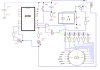
Now, I've sketched out some quick ideas of how it may work, but please be warned I am a complete amatuer :D And my schematics may be completely wrong.

I was hoping some of you guys and girls could help me out in any way you can? i.e. tell me where my design is wrong, suggest how I could achieve this with a completely different circuit etc.

Here are a couple of the thoughts I've had so far. (where the +9v comes in will be after a transformer)

**broken link removed****broken link removed**

I highly appreciate any help you can give me with this :)

Splash :delta:
 
Your circuits won't work without some refinement. I suggest you do a search of this forum. There have been plenty of timer circuits posted in the past. I've posted some myself.

There are three solutions:-
1. an RC timer - this requires a Schmitt Trigger to detect when the capacitor has charged to a particular level. It is a crude solution so you can't expect it to be very accurate.

2. A counter driven by a crystal or from the AC mains. This will be very accurate.

3. As for 2. but use a PIC instead of a counter. This is more flexible and will result in less components since the logic and counting is done in the PIC.

You have not indicated where you live. Several electronics shops sell kits in Australia.
See www.jaycar.com.au, www.altronics.com.au, www.dse.com.au
 
Last edited:
Hi Ljcox, thanks for the reply.
I've spent several hours searching the forum but havn't been able to find anything quite right for my project. However after googling for a while I came accross this circuit **broken link removed**

I was looking at the second of the 2 circuit designs as it de-energizes the relay and i.e. cutting power to the appliance.

However I was hoping someone could help me adapt the circuit to my needs either by redesigning or simply explaining where the extra components would need to go.

As far as I can see the circuit is missing the ability to be variably changed by a user, either by potentiometer or rotary switch.

Can anyone help me with this?

Oh and Im from england :) as is this circuit which is great as it tells me the component codes for maplins :D
 
Last edited:
Hi mcs51mc,
Thankyou for the links, those kits do pretty much exactly what I'm after they are variable by the changing of a jumper block which isnt really suitable as I want it to be very easy to use for people who arn't comfortable with poking around on PCB's plus I much prefer to make things from scratch, I find it far more satasfying :D

I've been playing with the 24 hour timer schematic and have come up with this, I would really appreciate it if someone could give it a look over and see if I have any big problems?

Thankyou all :D
 

Attachments

  • Timer Circuit.jpg
    Timer Circuit.jpg
    146.4 KB · Views: 270
Ah, on the above attached schematic I missed a flying wire between the 1st pole in the rotary switch and in between D1 and R5 :) just pretend its on there :p
 
That will work but it won't be that accurate; is accuracy important for your application?
 
Accuracy is important to a degree, as long as it isnt out by more that a few minutes it wont be a problem, do you think it will be less accurate than that?
 
That depends on the tollerance of the componants.
 
Ah ok, Im not sure of what tolerence effects, I'm assuming the only ones that would matter were the transistor, capacitors and relay? These are the components that I'm planning on getting. Any chance you could give them a once over?

**broken link removed**
 
No offence but obviously you've not been in engineering for very long.

A componant tollerance is the amount a componant value can vary from the stated value. The transistor and relay make no difference, the only componants that make a difference to the delay is the timing capacitor and resistors.

The capacitor is likely to have the largest tollerance so it will affect the delay more than the resistors. The capacitor has a tollerance of +-20%, therefor it can be as much as 20% bigger or 20% smaller than 10:mu:F, therefore its value can range between 8:mu:F and 12:mu:F.

Why are you using a more expensive non-polarised 100V electrolytic capacitor when a cheep polarised 10:mu:F 25V unit will do?

Non-polarised means it will work on AC, your project is DC so whilest it will work, it isn't required.

Look up the tollerance of the resistors, then recalculate everything for the upper tollerance value of capacitor and resistors then the lower tollerance values, then see if the level of accuracy is acceptable.
 
Haha no offence taken your completely correct.
Thankyou for explaining it makes sense now. I'm using the non-polarised capacitor as i was told it needed to either be non-polarized or 2 x 22uF Polarised back to back by the build instructions.

Ideally C3 should be non-polarized - but a regular electrolytic will work - provided it doesn't leak too badly in the reverse direction. Alternatively - you can simulate a non-polarized 10uF capacitor by connecting two 22uF capacitors back to back - as shown.

Ok, so all the resistors are +-5%

my original C1 & C2 were +80% which seems huge so I have changed to these;
**broken link removed** As they are +-20%

C3 is +-20%

So am I right in thinking it will be a maximum of 20% inaccurate?
 
Splash said:
my original C1 & C2 were +80% which seems huge so I have changed to these;
**broken link removed** As they are +-20%
All they are is decoupling capacitors, not timing capacitors so it won't make any difference. Please re-read my above post, you only have to worry about the components that directly effect the timing.


Splash said:
So am I right in thinking it will be a maximum of 20% inaccurate?
Yes, try using a crystal oscillator.
 
Ah ok, well for my project 20% would be about the limit of acceptable. Would using a crystal oscillator mean an overhaul of the circuit or simply adding something? ok I'll switch to a polarised cap.

Also I have never used mains power in a project before, I'm looking at this transformer **broken link removed**
Would a transformer like that output in DC? or will i need a seperate component to perform that function?
 
The output from that would be AC. You'd need to 'rectify' it to DC using either 4 diodes or a bridge rectifier.
There are many schematics on the net for power supplies.
 
You don't have to change the circuit completely, you only have to swap the oscillator section for a separate crystal oscillator. You'll probably need a separate oscillator and divider. I haven't done the calculation, what's the frequency of you existing RC oscillator?
 
Did you check the datasheet of the 4060?
There is another error in your schematic: You connect the reset circuit to pin 11, it should be pin 12.
Like Hero999 already suggest try using a Xtal. See datasheet for connections and values.

Or best choice:
Take the K6200 kit from Velleman.
Replace the dip switch SW3 with a Rotary DIL BCD switch.
Replace the PCB potmeter RV1 with a standard pot meter.
That way you also have PCB and all correct components.

You can dowload the schematic from the Velleman site.

Good luck...
 
Status
Not open for further replies.

New Articles From Microcontroller Tips

Back
Top