Continue to Site

Welcome to our site!

Electro Tech is an online community (with over 170,000 members) who enjoy talking about and building electronic circuits, projects and gadgets. To participate you need to register. Registration is free. Click here to register now.

  • Welcome to our site! Electro Tech is an online community (with over 170,000 members) who enjoy talking about and building electronic circuits, projects and gadgets. To participate you need to register. Registration is free. Click here to register now.

Made an amp in class need help troubleshooting it

Status
Not open for further replies.

polishdude20

New Member
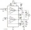
so i made an amp in class for your ipod its i think 20 watts. uses two TDA200SR for both channels so right and left. im using a transformer to take the wall voltage down to twelve volts . and so far only one side works while the other side hums VERY loudly like a motor boat i guess. and only one of the TDA200SR is getting VERY hot even with a small heatsink on the other one is just getting warm. so Im wondering without showing you guys the schematic ( dont have it with me) can you tell me what this problem can be? too low voltage? too high? anything you guys can think of?
 
well i read on the instructions we got that theres supposed to be a ground included in the IC or something like that so you dont attach a ground from the transformer. and i looked far and wide for the short but there are none i can find. could it be that i have a bad resistor or he wrong one? or anything else?
 
without a circuit, we are just playing 20 questions...
 
There is no such amp as a TDA200SR.
Maybe it is a TDA2003, TDA2004, TDA2005 or many other TDA amps.
 
sorry TDA2005 i misread it it was dark so sue me
if thats the only reason you came and replied then go away. i need help not parts corrections
 
Why are you so nasty? We are trying to help you.
You told us the wrong part number so how can we help you fix something that does not exist??

Did you use the circuit and parts shown in its datasheet?
Did you use the pcb design shown in its datasheet?
With a 12V supply and a 4 ohm speaker its output is 11W, not 20W.

If you connected the polarity of the power supply backwards then the TDA2005 IC is destroyed. the schematic on the datasheet is fuzzy but shows the positive pin is pin 9.
 

Attachments

  • TDA2005 bridged amp.PNG
    TDA2005 bridged amp.PNG
    16.9 KB · Views: 1,887
ok sorry . um anyways i didnt use that data sheet or the design . and im looking for any shorts right now and cant find any. can you point me in the direction by telling me were a short could be that its making that sound and heating up alot? and only one of the sides work without buzzing
 
The TDA2005 probably will not work if you don't use the schematic in its datasheet and don't use the pcb design shown in its datasheet.

Now you made another thread asking about the polarity of a transformer.
A transformer has an AC output that will destroy the amplifier ICs that need a DC power supply instead.
 
It is useless to discuss your circuit without seeing your detailed schematic.

Usually a full-wave rectifier is used to convert the AC into pulsing DC. Then a big filter capacitor smooths the pulses.
The full-wave rectifier has four diodes, not just one diode.
 
OK this is a new update i got the amp to work on a 9 volt battery but i want to do it from a power supply fro the wall. i made a full wave rectifier with 4 diodes and tried different ways of making it and apparently the current is now dc so its working but theres still a buzzing noise when i conect it. when i have the battery in it doesn't buzz at all plz help!
 
There must be a pretty big capacitor at the output of the rectifier to filter the pulses from the rectifier. 4700uf should work well.
 
Now what would a guy named AudioGuru, know about audio amplifiers? ;)
 
ok well i ditched the whole idea of wall plugin and all that stuff but thanks for the suggestion audio guru. today was my last day in my electronics course anyways so i cant really get my hand on parts easy BUT. Ive gotten this far.....: the amp is originally designed to run on 12 volts DC but it also is able for some reason to run off my 9 volt battery and you can boost the soudn WAY U THERE like pretty loud. now i would like to know how long that battery might last cause i know not very long but what are we talking about here? hours of play? minutes? days?
 
Minutes. I suspect you already know this by now. :D
 
The TDA2005 probably will not work if you don't use the schematic in its datasheet and don't use the pcb design shown in its datasheet.

Now you made another thread asking about the polarity of a transformer.
A transformer has an AC output that will destroy the amplifier ICs that need a DC power supply instead.

audioguru is right about the transformer part but you don't necessarily make a PCB for the circuit right away, you can breadboard it just don't be surprised if you get some oscillations occurring or if you start to pick up some random RF.

but for everything else that audioguru says, make sure you listen to it, and be nice. he's our friend and he's here to help :) plus he knows what he's talking about.

remember pushing the limits is how invention happens.
 
ok well i ditched the whole idea of wall plugin and all that stuff but thanks for the suggestion audio guru. today was my last day in my electronics course anyways so i cant really get my hand on parts easy BUT. Ive gotten this far.....: the amp is originally designed to run on 12 volts DC but it also is able for some reason to run off my 9 volt battery and you can boost the soudn WAY U THERE like pretty loud. now i would like to know how long that battery might last cause i know not very long but what are we talking about here? hours of play? minutes? days?

a wall plug in would have been a great idea. you just need to make a power supply for your circuit, this way you don't have to worry about any kind of problems from lack of constant power. on the other hand throw in a battery just to keep the noise down, sometimes power supplies have a tendency of letting a little power through.
 
Status
Not open for further replies.

Latest threads

New Articles From Microcontroller Tips

Back
Top