Continue to Site

Welcome to our site!

Electro Tech is an online community (with over 170,000 members) who enjoy talking about and building electronic circuits, projects and gadgets. To participate you need to register. Registration is free. Click here to register now.

  • Welcome to our site! Electro Tech is an online community (with over 170,000 members) who enjoy talking about and building electronic circuits, projects and gadgets. To participate you need to register. Registration is free. Click here to register now.

LV8907 Voltage motor problem

Status
Not open for further replies.
Hi,
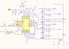
I have designed motor driver for electric scooter. This is my third version of PCB and something is wrong on it and i can't figure out how to solve the problem.
VS on your chip is 12V, and motor voltage is 24V.
If I lower the motor voltage down to 20V, everything works perfectly. At 24V everything is working at lower speeds. When i increase speed, motor doesn't get the power all the time (i have measured voltage between 2 phases, it looks like 50ms motor has normal PWM, and other 50ms motor is free spining generating sinusoidal voltage). But i repeat, i get it working in previous version without a problem, and now i cant figure out. So please help me
 

Attachments

  • lv8907 problem.PNG
    lv8907 problem.PNG
    132.8 KB · Views: 276
Okay.... I'm corrected...

But do check the CHP voltage input... to drive 24V I would have thought the Charge pumps should generate at least 22V.

The datasheet of the device "should" show a typical connection..
 
What is the peak voltage appearing across the current sense resistors?
With higher voltage (and presumably higher current), is it going in to some form of overload protection state?
 
Okay.... I'm corrected...

But do check the CHP voltage input... to drive 24V I would have thought the Charge pumps should generate at least 22V.

The datasheet of the device "should" show a typical connection..
Hm, maybe you are right.
So you think that now i get only 12V (vs) + 12V boost on high side fets? Which is not enough to turn them on. But my question is then why it works on low speeds?
What is the peak voltage appearing across the current sense resistors?
With higher voltage (and presumably higher current), is it going in to some form of overload protection state?
I havent checked but it should be much lower than current limit trigger. Because im testing this in free spining, and current is around 1A (and normally it would be above 20A)
 
See the first part of the ratings on page 9: Fully functional 5.5 - 20V; driver stage off up to 40V.

Also see figure 9 of the datasheet, on page 15.
The high side charge pump appears to be disabled once the Vs supply reaches 21V.

It's nominally a 12V device & not intended for high voltage supplies. The charge pumps only provide a certain margin (12V?) above Vs whilst they are enabled; go too high on the output supply and the upper devices will not have sufficient voltage to switch on.
Yeah, i know that all.
And you can see that i connected VS and other pins to 12V. I only want my motor to be on 24V, this chip is all @12V.
And the problem is that this way it all works till cca 40% of maximum speed. Every mosfet is turned on and off like it should be. And then suddenly everything is OFF, than ON and so on...
I think post #7 has already explained that?.
 
But the datasheet said up to 40V on the CHP pin via a suitable decoupling cap, so I would do this...
I have tried that, and even when CHP pin is connected to 24V, it still works the same way.

You can see on video what is happening, now i know that when motor doesnt run smootly, the reason is high side fets dont get Vgs voltage enough to turn them ON
When it falls bellow 4V, motor is not working properly. VS above 20V.
When VS is below 20V, the lower VS gets, higher Vgs is.


So i would assume that problem is somewhere in high side voltage pump. I tried changing C36 and C37 from 1uF to 4.7uF and it doesnt help either.
Does someone know what else can i try?
 
Im sorry, not VS but motor voltage.
The high-side gate drive voltage is set as 12 - 14V higher than VS!

It is not intended to run a motor on a separate supply, as all the output drive voltages directly relate to the IC supplies; high voltage motor drivers have a separate output section or use external device drivers.

I'm guessing the internal protection circuitry on the high side output pins is feeding power back through to the internal VS and tripping the device overvoltage detection, as soon as the upper transistors start switching on.
The device then goes in to overvoltage shut down until the voltage drops again, and the cycle repeats.
 
I have raised VS from 12V to 18.5V, and now motor runs perfectly (without overheating mofets because they get more than 8V).
So the answer is that you can run this on more than 20V, 24V in my case, but you need to have enough voltage on high side gates.
I dont know if i can try to put smaller capacitors to CP1 and CP2, but for now everything works till 27V
 
I was about to suggest around 15V, However! if JRW knows his stuff, the high side outputs are rated at 16V, Christ knows how long the internal components will last... I would chuck a fan on the chip just in case..
 
So the answer is that you can run this on more than 20V, 24V in my case, but you need to have enough voltage on high side gates.
I dont know if i can try to put smaller capacitors to CP1 and CP2, but for now everything works till 27V
The problem is that if the upper FETS can turn on properly and their drain supply is higher than VS, the high side source connection pins on the IC can be driven to a higher voltage than the device supply VS.

With many types of IC, forcing a pin outside the device supply pin range can cause damage, either immediately or long term due to repeated overloads of internal protection components.

You are using the device beyond the makers specification.

Some may work, some may not - and there is absolutely no way of knowing if any particular device will last a day, a week, or decades.
 
Status
Not open for further replies.

Latest threads

Back
Top