Continue to Site

Welcome to our site!

Electro Tech is an online community (with over 170,000 members) who enjoy talking about and building electronic circuits, projects and gadgets. To participate you need to register. Registration is free. Click here to register now.

  • Welcome to our site! Electro Tech is an online community (with over 170,000 members) who enjoy talking about and building electronic circuits, projects and gadgets. To participate you need to register. Registration is free. Click here to register now.

LTspice problem

Status
Not open for further replies.
Thank you for replying Torben

The cmp directory was on read only so i unchecked that but it still didnt work.
Then i thought why not make sure the entire LTspice folder is not on read only so i did and unchecked that too. Hope thats ok?

Well anyway I managed to save the cmp file in notepad :)

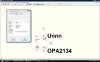
However when i open LTspice and right click on new transistor i do see the new transistor but its values of vceo and ic are zero :(

whats gone wrong ths time?

OK, getting closer anyway. :)

Can you attach your standard.bjt file to your next post?


Torben
 
I had to save it as a txt file as it wouldnt let me upload it as a .bjt file is that ok?
 

Attachments

  • standard.txt
    17.7 KB · Views: 279
Copy the complete C: file name above into your pasteboard.
C:\Program Files\LTC\LTspiceIV\lib\cmp\standard.bjt
Then go to the Windows Start button, and open the RUN command.
Paste the file name into the RUN block, and OK.
Go to the end of the model page, and copy/paste the data block.
 
Last edited:
Thank you for replying user

I have now managed to save the model as i mentioned above but the new problem is when viewed in 'new transistor' the values vceo and ic are zero
 
Thank you for replying user

I have now managed to save the model as i mentioned above but the new problem is when viewed in 'new transistor' the values vceo and ic are zero


Yes .... you need to locate some usable numbers for these specifications, and then modify the model file accordingly.

The model page has some examples .... not exactly sure what the correct numbers are for your transistor though.
 
Last edited:
Shouldnt the correct numbers already be there?

comparing the text for each model i see that the new model i downloaded does not have a vce written in its lines of text.
I guess thats why you said specify my own value. This is all new to me sorry if i'm slow.

I downloaded another transistor model from on semiconductor this time a 2n3773 and it also does not show vceo or Ic. Also it does not have in its text vce.

I guess on semiconductor don't include these in their models :(
How do i write in the vceo and Ic values i want for these transistors into the model text?
THey don't need to be in the model. If you want to know what the specs are, look in the datasheet. If you really want them in the model, you can edit standard.bjt with Notepad. To save as standard.bjt, change Save as Type: to All Files.
 
I know they dont need to be in order for ltspice to work but i would like them there so i dont have to look up what they are each time.

I dont know what to write in the text to make the vceo and ic i give it appear in the box in LTspice, for example assuming vceo is 40v and Ic is 1000ma how do i make that appear?
All you have to do is look at examples of transistors that do have values, and emulate how they are entered in standard.bjt. For example:
Code:
.model 2N3904 NPN(IS=1E-14 VAF=100 Bf=300 IKF=0.4 XTB=1.5 BR=4 CJC=4E-12 CJE=8E-12 RB=20 RC=0.1 RE=0.1 TR=250E-9 TF=350E-12 ITF=1 VTF=2 XTF=3 [COLOR=Blue]Vceo=40 Icrating=200m[/COLOR] mfg=Philips)
 
I have not worked out how to find an .asc file direct from manage attachments :(

However a reasonably acceptable method i am using is to open LTspice and send the file from there to documents and then find the .asc from documents through manage attachments

At least i don't have to wait ages to find it through the search now :)
 
I think i have a model for the OPA-2134 by having an include directive to the pspice model file saved as a text document.

Trouble is i dont know if LTspice is using the OPA-2134 parameters or the universal op amps parameters i originally placed as a component and then renamed.

How can i see if i do actually have an accurate OPA-2134 model?

I've attached my schematic

I dont seem to be able to attach the .mod file the link to the burrbrown site is here

https://www.ti.com/litv/zip/sbom042
 

Attachments

  • opa2134 test.asc
    1.5 KB · Views: 242
Last edited:
that's a windows file permission problem. whatever user you sign in as, you need to go in as the admin and set the user rights for that account as admin, or at least assign yourself admin rights for all of the LTspice folders.
 
thanks for replying unclejed

Sorry re reading what i posted i realize its unclear.

When i say 'how can i see if i do have an accurate model of the opa-2134'
i mean i how do i know its an accurate model.
I can access the schematic i made fine, what i need is a circuit that will show the difference between the response of an opa-2134 and another op amp.

I ran a dc operating directive for the opa-2134 in the circuit i've attached and then i ran the same circuit but with a general opamp (called universal opamp in LTspice) and the results were exactly the same (current through feedback resistors exactly the same for example).

As my model was originally the 'universal op amp' before i renamed it and told LTspice to use the opa-2134.mod instead, i'm unsure if my model has the characteristics of the opa-2134 or the 'universal op amp'

I may not need a circuit i may need to just change some component values? Any ideas appreciated
 
Last edited:
Put two identical circuits on the same schematic, but make the op amps different. Run an AC sweep from 1kHz to 100Mhz and look at the Bode plots (frequency response) of both outputs. Also, try a time domain sim with square waves as the inputs. Try 1MHz square waves with 50nS rise and fall times.
You can use the same voltage source for both inputs.
 
Last edited:
look at the netlist under View>Spice Netlist, and see what model it's using. sometimes it will also list internal nodes of the model. you can then compare that info with the model itself.
 
Well i seem to have made some progress :)

It turns out i did not have a model of the OPA2134, my mistake was using the 'universal op amp' as the base component before adding a spice directive to the OPA2134 sub circuit.

When i used the 'op amp2' component as the base i think i have achieved an OPA2134 model, the result is shown on the screen print 14 below, is that what it should look like?

However i don't like having to have an include directive or alternatively pasting the .subcrkt instructions into the schematic so i have attempted to create a OPA2134 component.

I copied the 'opamp2' .asy file then renamed it OPA-2134.
I then edited the attributes to that shown in screen print 15 below.
I moved the OPA134.mod file into the sub folder.

When i inserted this new component into my schematic i no longer needed the spice directive or pasted subcrkt so it appears i have a working model! :)
At least the results are the same as shown in screenprint 14

Could you please confirm that Vout2 shown in green is what you would expect an OPA-2134s output to look like

(the blue vout is just an LT opamp i picked randomly to compare with my OPA-2134)
 

Attachments

  • screen print 14.jpg
    screen print 14.jpg
    215.4 KB · Views: 389
  • screenprint 15.jpg
    screenprint 15.jpg
    91.3 KB · Views: 333
  • opa2134 test2.asc
    2.6 KB · Views: 259
Last edited:
It looks good. You might want to consider that it is not simple to create a new symbol for each op amp you want to use.
I put all my subcircuits into the /lib/sub folder. Then, your include directive is simply .lib OPA2134..mod, or whatever the name of the subcircuit file is called.
 
Status
Not open for further replies.

Latest threads

New Articles From Microcontroller Tips

Back
Top