Gee Won Han
New Member
Hi,
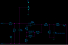
I am getting an error: "Unknown subcircuit called in: xu1 n007 n002 n004 opamp aol=100k gbw=10meg"
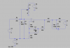
The design has a microprocessor attached at the end of the design. The J2-1 and J2-2 is where the Piezo is connected. The processor gives out a PWM initially to charge the circuit.
Then the processor goes into an input mode. Once the piezo is press the output sends a high signal to the processor.
I am not sure if I replicated the design on LTSpice correctly. Of course LTSpice doesn't have a processor.
I am getting an error: "Unknown subcircuit called in: xu1 n007 n002 n004 opamp aol=100k gbw=10meg"
The design has a microprocessor attached at the end of the design. The J2-1 and J2-2 is where the Piezo is connected. The processor gives out a PWM initially to charge the circuit.
Then the processor goes into an input mode. Once the piezo is press the output sends a high signal to the processor.
I am not sure if I replicated the design on LTSpice correctly. Of course LTSpice doesn't have a processor.