Continue to Site

Welcome to our site!

Electro Tech is an online community (with over 170,000 members) who enjoy talking about and building electronic circuits, projects and gadgets. To participate you need to register. Registration is free. Click here to register now.

  • Welcome to our site! Electro Tech is an online community (with over 170,000 members) who enjoy talking about and building electronic circuits, projects and gadgets. To participate you need to register. Registration is free. Click here to register now.

Ltspice Advice

Status
Not open for further replies.

Quantised

Member
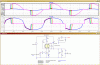
I was wondering if Ltspice would give any good output about the circuit below. As I have never used it before it will be a big learning curve but do you think it is worth the effort to see if the circuit is good and will it allow me to tweak components to see if it can be improved ? Probably wont use it again either!

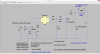
The transformer is unknown so something of a similar size will have to used to get a model for it and that alone may be too much of a guess to invalidate any analysis.

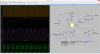
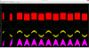
Will Ltspice be able to see if the phase etc for the triac is correct? Of course the other big question is will I even be able to interpret the results!

Triac is a BTA26 and the optocoupler is a MOC3021

Triac circuit.JPG
 
I have simulated AC phase-controlled SCR and Triac circuits with LTSpice and got good agreement with real circuits. Models are out there, but a bit hard to find...

Modeling transformers is hard, especially if you are trying to account for non-linear behavior. Not that the way LTSpice models transformers is inadequate, but you have to know how to do it (which I learned I don't).
 
Since a power transformer is generally mostly transparent to the circuit you can just use an AC source to simulate it.

The difficult part may be to find an appropriate SCR model, as Mike noted, since there are none included in the LTspice library.
 
hi,
Try these LTS Triac files in this zip.
E
 

Attachments

  • triacs1.zip
    9.6 KB · Views: 787
Hi

Here is a TRIAC Library from STMicroelectronics. I've included a modified LTspice TRIAC symbol to maps the pins correctly.

The library has the BTA26.

eT
 

Attachments

  • st_standard_snubberless_triacs.zip
    5 KB · Views: 644
  • Dimmer.png
    Dimmer.png
    418.3 KB · Views: 1,519
Thanks for all the comments and the lib files. Have not had time to try them yet as I have only downloaded spice a few hours ago and have been using a triac and diac model that was in ltspice just to get a feel for the program. I will try the BTA26 model once learned how to do it.

I tried R3 from 22 up 2.2M and the results were almost the same and added a coil with various H values, but I see a double spike in R1 current which is confusing.

But I think the problem I have is the diac is fired by the control circuit and how do I model that???? It is opto coupled package so assume the controller shortens the 'on' time by sending shorter pulses - guess of course.

Probably need a model of a MOC3021 and generate a pulse train to fire it.

ltspice run.JPG
 
Hi Quantised

Here's the circuit with the models you need.;)

eT
 

Attachments

  • Dimmer2.zip
    8.5 KB · Views: 618
  • DImmer2.png
    DImmer2.png
    617.5 KB · Views: 1,605
eT - Wow that is really great and is just what i have. Thankyou so much for your kind effort.

Have been playing around with different values for R3 and the snubber circuit and seems when R3 is 22 or less the thing stops working but when 25 or more it is stable. Even at 2M it still produces the same waveforms. (almost) been running different values for hours now.

But I cannot find a way to turn the circuit down ie dim the light. I tried changing the pulse freq, duration, on/off period etc but I cant get it to turn down, do you know how the thing is turned up and down?

R3 50ohms.JPG
R3 22 ohms not looking good.JPG
 
Hi

I wasn't really focused on the circuit design, I was more focused on providing models and a sim.:(
But...it looks like the opto is configured to pulse the internal diac, via the LED, allowing control of the TRIAC "on" time. So the lamp will brightness can be controlled.

But I cannot find a way to turn the circuit down ie dim the light. I tried changing the pulse freq, duration, on/off period etc but I cant get it to turn down, do you know how the thing is turned up and down

It works for me. If I change the frequency on V2 (period and on times) the power thru the bulb changes.
Lower the freq and the power increases, raise the freq and the power decreases.

I don't think you need R5 C1 and Rload, or the LoadPower circuit though...
You can plot the power thru the bulb by using V(A)*Ix(LAMP:A) in a graph.

eT
 
To plot power dissipated in a device with LTspice just press the ALT key while hovering over the device. When you see the thermometer symbol, left-click to plot the power.
 
I have set R3 to 33 as when it is 22 the simulation only shows like 30v going to the load, when 33 is used it seems to work better and shows 160v going to the load.

Now I try every permatation of pulse but cannot get it to turn up or down the load. Obviously doing something wrong but cannot figure out what.

Maybe I will have to measure what goes into the MOC3021 and vary the power output and see how it changes the drive to the LED.
 
hi Q,
Please post your LTS asc files so that we can run them.
E
 
Hi Eric - the one I am running is the one called dimmer2.zip kindly posted by eTech in post#7 and I run it with R3 as 22 but the output seems all wrong but quite OK when set to 33.

Tried setting R1 to 330 and that allows the R3 to work at 22 so assume it is on the border.

Trying to get the output to look like the scope trace I get of the output.
 
hi Q,
Its too marginal with a 22R on R3, I would suggest a 33R.
Look at this sim for R1 20R thru 40R in 5R steps.
Note: it does not trigger the Triac at R3 = 20R in the Sim.

E

BTW: Are you aware that there is no user isolation from the mains supply.?
 

Attachments

  • AAesp03.gif
    AAesp03.gif
    45.4 KB · Views: 665
Hi Eric

I tried the same simulation and also see the trigger points, extended the sim to 20 up to 520 in steps of 50 and the trigger point seems to converge to the same position on the AC curve when R3 is around 300. Is that relevant as I am not sure how to calculate or select the best value for R3. It also lowers the diac current.

Is it bad to have the triac fire earlier in the AC cycle?

About the AC isolation, do you mean the driver circuit of Q1, as I tried to isolate it in the model and LTSpice gives an error. In real life it is isolated by the opto coupler and is driven solely from the 12v supply rail.
 
Hi eT

Yes it is controlled by a SG3524, basically that controls the Q1 as you drew it so the SG does the job of the pulse. Still cant get it to turn down the power yet.
Also added a transformer, a bridge and a battery like the real one but it makes little difference.
 
Hi Q

Take a look at the attached.

Dimmer6 is a modified version of the circuit you posted.
Dim50Percent shows the load power at 50% duty cycle
Dim100Percent shows the load power at 100% duty cycle.

The CTL Pulse frequency is 60Hz
Below is a listing of the load power with the CTL pulse varied from 50% to 100% duty cycle:

Circuit: * Dimmer6.asc
Direct Newton iteration for .op point succeeded.
.step t=0.00833
.step t=0.009163
.step t=0.009996
.step t=0.010829
.step t=0.011662
.step t=0.012495
.step t=0.013328
.step t=0.014161
.step t=0.014994
.step t=0.015827
.step t=0.01666

Measurement: lampwatts
step AVG(v(a)*ix(lamp:a)+v(b)*ix(lamp:b)) FROM TO
1 52.2623 0 0.1
2 52.3424 0 0.1
3 54.1107 0 0.1
4 58.4725 0 0.1
5 65.9663 0 0.1
6 78.5623 0 0.1
7 85.8057 0 0.1
8 91.5466 0 0.1
9 94.979 0 0.1
10 96.1756 0 0.1
11 96.1753 0 0.1

Also, attached is a new lamp.txt model file. Replace the one you have with this one.
The previous one had a error.

Hope this helps.

eT
 

Attachments

  • Dimmer6.png
    Dimmer6.png
    408.8 KB · Views: 786
  • Dim50Percent.png
    Dim50Percent.png
    314.1 KB · Views: 557
  • Dim100Percent.png
    Dim100Percent.png
    368.2 KB · Views: 471
  • lamp.txt
    765 bytes · Views: 253
Hi eT - what happened to R3 the 22ohm from trig to ground. It seems it should be there as that is what the actual circuit has.

Trying to get the real life data on the input but slowed by no right hand - maybe tomorrow I can get it as that would help.

If you have the .asc I can try it.

This is connected to the 339 circuit we have been discussing as that circuit feeds the SG which in turn drives the triac so if it is borderline then what may be the cause of the pulse.
 
Status
Not open for further replies.

Latest threads

New Articles From Microcontroller Tips

Back
Top