Continue to Site

Welcome to our site!

Electro Tech is an online community (with over 170,000 members) who enjoy talking about and building electronic circuits, projects and gadgets. To participate you need to register. Registration is free. Click here to register now.

  • Welcome to our site! Electro Tech is an online community (with over 170,000 members) who enjoy talking about and building electronic circuits, projects and gadgets. To participate you need to register. Registration is free. Click here to register now.

Low Frequency AC->DC for 5V USB Buck

Status
Not open for further replies.
If you could hand write your circuit, that would be great. Draw and scan, or photo.
 
From your post 18 it is clear that you do not understand how a transistor behaves. Any circuit designed based ane these false assumptions will not work. In post #1 you say "the frequency is low and this causes the circuit to burst 5v" I do not understand understand what you mean by frequency as the input is DC. (I only thing I can think of is that the dynamo gives AC output and you are rectfying it.) Also what do you mean by "burst 5V" ? We are all trying to guess what your circuit is as none of us have a crystal ball. The circuit below MAY do what you want.

Level_Detector01.jpg


This is how it works. When the input voltage is above the zener voltage + about 0.7 volts (Vbe of the transistor Q1) Q1 will conduct. This will short out the base drive to Q2 from R3 so that Q2 does not conduct so C1 can charge via R5 and the diode. If the input voltage is below the zener voltage + about 0.7 volts Q1 will not conduct. This will cause Q2 to conduct (Due to current into it's bse from R3) which shorts out C1. Choose the value of R4 to limit the collecter current of Q2 to within it's ratings. The diode above R5 is only to prevent C1 from holding up the input voltage via R5. The diode is probably not required. You will have to work out the component values as you have not provided enough information for us to do so. You may be able to use a comparitor chip such as the LM393 but you have not provided enough information to know if this chip would be used within it's ratings. IF the input is from rectified AC then you could use the ripple frequency instead of the voltage level to decide when to enable the regulator. I was tempted to just give a description of the circuit to make it just as hard for you as you are making it for us but I decided it was quicker to draw the circuit.

Les.
 
Last edited:
An important feature of the converter is under-voltage lockout, so that it doesn't operate until Vin rises above a suitable threshold. That ensures the internal switching FET can switch on fully and won't overheat. If the bike starts and stops, so must the converter (thus interrupting USB devices, unless you have a battery to power it when the bike is moving slowly or stopped). I now don't see how adding the capacitor is beneficial, since it doesn't affect Vin. The converter should operate only when the bike/dynamo speed is high enough to maintain Vin greater than the threshold voltage.
Does your dynamo put out rectified AC, or does it put out AC and need an external rectifier? Do you have a large smoothing capacitor on the dynamo/rectifier output to ensure a steady Vin?
 
Last edited:
Does your dynamo put out rectified AC, or does it put out AC and need an external rectifier? Do you have a large smoothing capacitor on the dynamo/rectifier output to ensure a steady Vin?
If this is the same as last months project; AC and the frequency gets down to 10hz, and at that point the voltage is so low there is no "head room" so it really needs a large capacitor. But there is no room for a large cap.
 
HI all, sorry for my delay. I've been busy...

Input AC - 6V, but frequency varies. Ultimately it's not the voltage that I need to detect but the frequency as there are still 6V "bursts" right down to 1/2hz. Capacitors either side of the switch mode don't elevate the problem.

Since writing the post yesterday I've been playing around and have made good progress. I'll find some Linux schematic software tomorrow and post up a diagram, but for now;

Using a 555/monostable or doesn't work due to capacitor being unable to discharge before the next V+/Hz. Attempts to discharge the capacitor have all failed due to unreliable power source to keep a transistor latched, and the varying frequency which requires hysteresis to solve.

To get around this I tried a 4060 with a diode on the last output to latch the enable pin. This works great but the chip requires a minimum 20uF for stability so I can't reset it using low V+/Hz alone. It has a reset pin though, so...

I tried a 741 wiring a equal voltage divider to vin and vref (same both sides), but using a small capacitor on one of the divider sides. My thinking was as the V+ became "choppy" the capacitor would delay the voltage and the output would begin to cycle, which would trip the reset on the 4060.

However the capacitance for the switch mode and 4060 prevented this happening, and the switch mode was potentially draining the 4060 supply, so, I added four additional diodes and give each it's own V+ rail. Hence the 741 vin/vref are monitoring V+ without any capacitor smoothing.

I'm now very close. The 741 just misses the beginning of the low frequency before resettting the 4060 and keeping it reset. I've tried all sorts of tiny capacitor and resistor dividers to tweak it but haven't had any success. Perhaps it is pulsing and the 4060 isn't quick enough (I have only an LED to inspect the 741 output). I'm wondering if an NE567 would be a better option (if it's possible?).
 
From your post 18 it is clear that you do not understand how a transistor behaves. Any circuit designed based ane these false assumptions will not work. In post #1 you say "the frequency is low and this causes the circuit to burst 5v" I do not understand understand what you mean by frequency as the input is DC. (I only thing I can think of is that the dynamo gives AC output and you are rectfying it.) Also what do you mean by "burst 5V" ? We are all trying to guess what your circuit is as none of us have a crystal ball. The circuit below MAY do what you want.

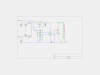
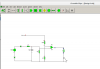
View attachment 98178

This is how it works. When the input voltage is above the zener voltage + about 0.7 volts (Vbe of the transistor Q1) Q1 will conduct. This will short out the base drive to Q2 from R3 so that Q2 does not conduct so C1 can charge via R5 and the diode. If the input voltage is below the zener voltage + about 0.7 volts Q1 will not conduct. This will cause Q2 to conduct (Due to current into it's bse from R3) which shorts out C1. Choose the value of R4 to limit the collecter current of Q2 to within it's ratings. The diode above R5 is only to prevent C1 from holding up the input voltage via R5. The diode is probably not required. You will have to work out the component values as you have not provided enough information for us to do so. You may be able to use a comparitor chip such as the LM393 but you have not provided enough information to know if this chip would be used within it's ratings. IF the input is from rectified AC then you could use the ripple frequency instead of the voltage level to decide when to enable the regulator. I was tempted to just give a description of the circuit to make it just as hard for you as you are making it for us but I decided it was quicker to draw the circuit.

Les.

Sorry, the last time I used schematic software was crocodile clips. I'll have to get something similar to avoid my arcane descriptions!

Ripple frequency detection looks like what I need, possibly integrated with the 4060 to provide a delay, if it's even needed. Any suggestions!?
 
Diagram attached. It's incomplete, missing 4060 RC. The main area of focus is detecting the AC ripple/frequency. I'm very close and will upload a youtube vid in a bit to show it.
 

Attachments

  • d1s.png
    d1s.png
    40.8 KB · Views: 154
Here's what I came up with for the voltage comparison. The 741 would be on the 'smoothed' 5v rail, so I'd have to zener clamp the input to keep the comparison consistent. Can anyone see any problems?

It works in Crocodile Clips from 1998!
 

Attachments

  • Screenshot from 2016-03-19 21-57-00.png
    Screenshot from 2016-03-19 21-57-00.png
    12.6 KB · Views: 150
This is my suggested circuit.


LV_Shutdown01.png

This is how it works The raw rectified waveform before smoothing is taken via a resistor and zener diode to the base of T1 so T1 only conducts when the input voltage is above 5.3 volts. This generates pulses at the collector of T1. These pulses go to the re-triggerable one shot so that if the time between the pulses is less than the time constant of the one shot the Q output remains high and the not Q remains low. These pulses also clock the 4017 counter. When it reaches a count of 9 the Q9 output inhibits further counting and Q9 remains high. this is used to enable the main regulator chip. As soon as the frequency goes below the re trigger time of the one shot the one shot's not Q output goes high reseting the 4017. After the input frequency is high enough the not Q output of the on shot goes low removing the reset from the 4017. It then needs another 9 pulses before the main regulator is re enabled. If I was doing this I would use a single ATtiny13 or PIC12F629 microcontroller.

Les.
 
I concur, it makes more sense, plus I'm a programmer so picking up the pic stuff shouldn't be difficult. Pickit2 and 50x 629's ordered!

I take it the programming side of it is just sampling the logic at the pin and turning another on/off, with another bit of simple logic for hysteresis.
 
You can look at a pin for 1 or 0, or you can get a part that can measure voltage.
If voltage is over 3 volts or under 2 volts = hysteresis.
There are a number of ways to set up a time delay.
The 16F629 does not have analog in but you can use the analog compare with two resistors to get hysteresis. It will burn 3 pins.
Use the 4mhz internal oscillator.
 
I was thinking a 6v zener & resistor and another 12v zener for protection into the 629 input then polling with a buffer to check last values, if all are 1 then enable output. This way it's frequency not voltage based.
 
If you size the resistors so the current is less than 1mA there should not be a problem. Note the diodes to gnd and supply for input protection.
You could set the analog comp to switch at 1/2 supply. (micro's supply)
 
Will do. If 6v AC = 8.46V I'm thinking a 4V zener to give (ideally) 4.46V and a 5V zener for protection. I'm assuming 5V at minimal current will be fine for the 629 input pin.

Going to be a good project this!
 
I haven't thought this through have I - just because the frequency changes the amount of detected '1's will retain the ratio to the amount of '0''s detected.

Or have I, the zener would limit the input to the top of one cycle and there would be more of them. So that works. Hmm!
 
You could look for "zero crossing". (when no power is being output)
Look for the edges.
I must see an edge every x-many milliseconds or shut down.
 
Here are a few thoughts on using the micro. My initial thought was to emulate my circuit in post #29 but wait for more than 9 pulses without a drop below the low frequency threashold. Using the micro makes it easy to adjust the timing. If you go down the voltage testing method then a PIC12F675 has an analogue input. Both pics have an analog comparitor input that could be used for voltage level sensing. You could even add hysteresis by connectin a resistor betweem an output pin and the comparator reference input to change the reference voltage.

Les.
 
Hi Les, I'm also wishing to go down this route.

I've attached my initial design. What I can't get my head around is if the dynamo is at low hz, the amount of time spent at a positive voltage within a given timeframe is exactly the same as a high frequency. Sampling it at higher frequencies I'd expect

1010101010101010

And at low frequency

1111000011110000

So I take it all I need to do is ensure there's no 0's in sequence for a given period of time.

Back to the circuit;

1. Would the 7805 be overkill? I'd be using the To92 casing but the 629 takes so little current a resistor and 5v zener may be simpler?
2. C1 prevents the 629 resetting at low Hz. Probably 6.3 470uF
3. R1 is 10k, required to pull the buck low by default
4. Z1 would be 4V. R? would be large say 1m. Max AC input is 17V clamped by two beefy zeners (not shown).
 

Attachments

  • usb.png
    usb.png
    19.7 KB · Views: 136
Status
Not open for further replies.

Latest threads

New Articles From Microcontroller Tips

Back
Top