Continue to Site

Welcome to our site!

Electro Tech is an online community (with over 170,000 members) who enjoy talking about and building electronic circuits, projects and gadgets. To participate you need to register. Registration is free. Click here to register now.

  • Welcome to our site! Electro Tech is an online community (with over 170,000 members) who enjoy talking about and building electronic circuits, projects and gadgets. To participate you need to register. Registration is free. Click here to register now.

Looking for P-channel equivalent of an IRF510 Power MOSFET

Status
Not open for further replies.
Hi Dino,
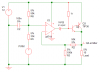
I'm glad you discovered the "Suzluki" pair of a darlington type of connections for complimentary transistors. It has the voltage loss of a single transistor but a high current gain.

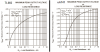
The 741 has a little higher output voltage than the TL081, but over only part of its output current range. There are a few dual 741 opamps: MC1458 and 4558 ring a bell in my mind.
 

Attachments

  • opamps_comparison.png
    opamps_comparison.png
    19 KB · Views: 720
Here's a way you can do it with a PMOS output transistor. I put it inside the feedback loop, so with 0 to 4.2V in, you will get exactly 7 to 11 volts out. You could get even higher output by altering the resistor networks.
You can change R2 and R7 (keeping the ratio the same) if you need less filtering, or you could change C2. I suspect you already know this.

Optionally, you could put your Darlington emitter follower inside the loop, but even with a rail-to-rail op amp, you would not be able to get more than about 10.6V out. Putting the driver inside the loop makes the output voltage more predictable, and insensitive to temperature and load changes.
 

Attachments

  • pmos_amp.png
    pmos_amp.png
    15.8 KB · Views: 2,647
audioguru said:
I tried simulating it, but the Mosfets in my software have static damage.

You should always wear a ground strap before opening the file containing MOSFET models.
 
Other than the maximum voltage that I can get, is there any real difference to using a power transistor vs. a pfet? pfets are hard to find locally.

What is the purpose of C1? Does this just filter the PWM even more? Or is it important because it is on the output of the opamp? Is it a way of keeping the op-amp from responding too quickly to "noise"?
 
dinofx said:
Other than the maximum voltage that I can get, is there any real difference to using a power transistor vs. a pfet? pfets are hard to find locally.

What is the purpose of C1? Does this just filter the PWM even more? Or is it important because it is on the output of the opamp? Is it a way of keeping the op-amp from responding too quickly to "noise"?
If you don't have C1 and R8, the circuit will probably oscillate.
The R3/R4 resistive divider does several things (this sounds irrelevant - bear with me). It shifts the output voltage of the op amp toward the center of the supply range, it isolates the op amp from the capacitive load of the MOSFET, and it helps reduce the loop gain (as does R5 & R6), which has been increased by the gain of the MOSFET. If the loop gain is too high, the circuit can oscillate. R3/R4 and the MOSFET input C also add a pole which will cause oscillation. C1 prevents oscillation by providing a high frequency feedback path.
The advantage of the PMOS is, as I stated, that your output can get closer to the supply voltage than is possible with an NPN Darlington, which you said was desirable. You could probably use a PNP Darlington in place of the PMOS. In either case, note that the feedback is to the noninverting op amp input. This is because the PMOS (or PNP) inverts.
 
dinofx said:
Thank guru. I see that if I want to maximize my maximum output voltage, I need to draw less current from the TL082, and/or use a ua741. The revised design has a maximum output of 11 vs 10.4 before.


....


The TIP36 is overkill, I'm actually going to use the TIP41/42, but I couldn't find a spice model for it.

.

In case you go back to bipolars... here's a TIP41 model.

*PART NUMBER: TIP41
*MODEL NAME: TIP41
*SYMBOL: QNPN
*SYNTAX: Qname c b e TIP41
*
* Power bipolar transistor
*
.MODEL TIP41 NPN (
+ IS=4.575E-013 XTI=3 EG=1.11 VAF=50 BF=156.7
+ ISE=1.346E-012 NE=1.34 IKF=3.296 XTB=2.2 BR=7.639
+ ISC=6.041E-013 NC=2.168 IKR=0.008131 RC=0.09129 CJC=2.787E-010
+ MJC=0.385 VJC=0.75 FC=0.5 CJE=4.33E-010 MJE=0.5
+ VJE=0.75 TR=1.412E-006 TF=3.734E-008 ITF=35.68 XTF=1.163
+ VTF=10 RB=0.1 )


Lemme know if you need A,B,C or the TIP42A,B or C

For the audience, the configuration is "Sziklai" transistor pair sometimes called the complimentary darlington. Not any easier to pronounce than Audio's massacre of the term. :lol:
 
I don't have a PFET, so here's my latest rev. Please let me know where you think a feedback capacitor is needed. The final values of resistors may be adjusted, but let me know if I am missing a resistor somewhere.

According to simulation, I can get a maximum of 10.95 volts from this approach. Anything over 10 is going to work.
 

Attachments

  • pwm.gif
    pwm.gif
    7.7 KB · Views: 892
My bad, it's the TIP42 from Radio Shack. No letter after it, whatever that means.

Hmm. could it be:
Code:
.model TIP42   PNP(Is=66.19f Xti=3 Eg=1.11 Vaf=100 Bf=137.6 Ise=862.2f
+               Ne=1.481 Ikf=1.642 Nk=.5695 Xtb=2 Br=5.88 Isc=273.5f Nc=1.24
+               Ikr=3.555 Rc=79.39m Cjc=870.4p Mjc=.6481 Vjc=.75 Fc=.5
+               Cje=390.1p Mje=.4343 Vje=.75 Tr=235.4n Tf=23.21n Itf=71.33
+               Xtf=5.982 Vtf=10 Rb=.1)
 
dinofx said:
I don't have a PFET, so here's my latest rev. Please let me know where you think a feedback capacitor is needed. The final values of resistors may be adjusted, but let me know if I am missing a resistor somewhere.

According to simulation, I can get a maximum of 10.95 volts from this approach. Anything over 10 is going to work.

I think the feedback cap shown in RON's fet version remains suitable for this one as well.

If you require over 10 volts to work, you ought to calculate the minimum you can get with your offsets & tolerances. Otherwise, when you build the thing you may find it running under 10V (unless you will be cherry picking your R's)
 
My 741 model only allows about 10.3 V at the output - and that ain't guaranteed. Maybe you were monitoring the op amp output?
Anyhow, you can get closer to +12V by adding a zener and resistor as shown, since it is the op amp that is limiting your range. Either that, or switch to an op amp with rail-to-rail output capability.
 

Attachments

  • pwm1.png
    pwm1.png
    9.8 KB · Views: 1,668
Optikon said:
For the audience, the configuration is "Sziklai" transistor pair sometimes called the complimentary darlington. Not any easier to pronounce than Audio's massacre of the term. :lol:
Hee, hee. :lol: Sorry for the terrible spelling. I knew it was wrong when I entered it into Google and the results were: "Huh?"

I thought I invented it in about 1969 then saw it later in Radio-Electronics magazine. I found out about Sziklai's name a couple of years ago at Amps Lab.
 
Ron, what happens if the load has an internal capacitor? If there is a capacitor slowing the feedback, it looks like you get huge oscillations.
 
dinofx said:
Ron, what happens if the load has an internal capacitor? If there is a capacitor slowing the feedback, it looks like you get huge oscillations.
We have several different circuits now. How about posting the one you're asking about?
 
The trick with the zener diode is pretty slick.

I built the circuit on a breadboard and ran my pump for about 20 seconds and it start up at around 8 volts. (duty cycle is around 20% at boot-up). The transistor got really hot. It would have been burning about 4 watts, but it may have been oscillating. I'll be putting on a heat sink.
 

Attachments

  • zener_627.gif
    zener_627.gif
    6.3 KB · Views: 716
I see that that 50p capacitor directly connected to the negative input and amp's output solves the oscillation problem.
 
OK, but it's rated at 65W. Is the heatsink always going to be connected to the connector, or only on manufacturers that indicate it as a 4th terminal? In other words, do I need to worry about the heatsink touching any piece of metal (ground) in my computer case. I guess a volt meter will always answer that question...
 
dinofx said:
OK, but it's rated at 65W. Is the heatsink always going to be connected to the connector, or only on manufacturers that indicate it as a 4th terminal? In other words, do I need to worry about the heatsink touching any piece of metal (ground) in my computer case. I guess a volt meter will always answer that question...

The casing is connected to the collector (which is almost universal on power transistors) - it might be rated at 65W, but that's with an impossibly large heatsink, one which keeps the device at 25 degrees centigrade.

Incidently, in Towers (the leading transistor data book), a TIP31 is listed as 40WC (that's while kept at 25 degrees C), the higher spec TIP41 is listed as 2WF (that's only 2W in free air - no heatsink). I've never understood why they are listed completely differently?.
 
The chip inside a power transistor is always much hotter than its case. Its max power rating is with its case impossibly cooled to 25 degrees C and its chip at its absolute max temperature, where its reliability is questionable. Even power-cycling it might fracture the chip due to extreme heating and cooling, expansion and contraction.
 
Got the heatsink on and the feedback capacitor in place. It works exactly as simulated. Max voltage, 11.05, min voltage 7.34 or something. The heatsink is too hot to leave your finger on it, but not hot enough to boil saliva ;-). I used silver thermal compound when attaching.

Is this too hot? It is possible to run two TIP42s in parallel, or do they need to be "load balanced"? I'm starting to see why a buck converter is the preferred method for DC to DC.

Finally, I have a 10-Ohm 10W power resistor I could put in parallel around the TIP42. In this setup, it would take just over half the current load at the minimum voltage, which is going to be most of the time.
 
Status
Not open for further replies.

Latest threads

Back
Top