Continue to Site

Welcome to our site!

Electro Tech is an online community (with over 170,000 members) who enjoy talking about and building electronic circuits, projects and gadgets. To participate you need to register. Registration is free. Click here to register now.

  • Welcome to our site! Electro Tech is an online community (with over 170,000 members) who enjoy talking about and building electronic circuits, projects and gadgets. To participate you need to register. Registration is free. Click here to register now.

Looking for help adding a frequency counter to airband receiver

Status
Not open for further replies.

avz

Member
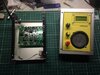
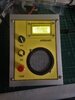
Hi. I've built a kit of an airband receiver purchased from Aliexpress. surprisingly, it even works. I've seen on youtube a clip demonstrating adding a frequency counter that displays the frequency. unfortunately, it's all in Russian, which of course I don't understand. attached are the circuit diagram of the receiver (it's the last page) and the link to the frequency counter (from Aliexpress, as well) that I would like to connect to it. could you tell me to which points on the receiver I have to connect the counter's input?
the link- **broken link removed**
Thanx.
 

Attachments

  • Aviation.pdf
    783.7 KB · Views: 262
The tuning is controlled by the local oscillator; I'd expect the take-off point for a frequency display to be from pin 7 of the NE602, via a buffer amp to minimise loading on that.

However, you the LO is offset from the receive frequency by the IF frequency, 10.7 MHz.
To display actual receive frequency it needs a counter that allows for that offset.

Possibly the Russian article for the display mod was offering an alternate PIC that had that included?
 
Thanx for your response. could you please explain in more plain English the second paragraph?
as per the Russian clip, all he showed how he put together on a wood base the receiver, the counter (which as much I was able to see was connected directly to the receiver - without any buffer) and a 9V battery.
 
I think "rjenkinsgb" assumed the frequency counter module only displayed the frequency applied to it's input. If that was the case it would display the local oscillator frequency rather than the received frequency. If that was the case the firmware in the PIC used in the frequency counter module would have to be modified to add or subtract (Depending if the LO was on the low side or the high side of the received frequency.) 10.7 Mhz to the local oscillator frequency. I found information in english for the frequency counter module and that implies that the display can be offset by the IF frequency. This is the link to the english version
https://www.aliexpress.com/item/400...earchweb0_0,searchweb201602_,searchweb201603_


Les.
 
I found information in english for the frequency counter module and that implies that the display can be offset by the IF frequency.
Well spotted!
I actually see that link in Italian for some reason, but it definitely mentions an IF offset capability in that page, so should do the job perfectly.
 
Re post #6. I think it must use a prescaler chip to divide down the input frequency. (I would guess at a divide by 32.) There was a design in the EPE magzine November 2008 using a PIC16F628A (Same as PIC16F648 but less memory.) the read up to 50 Mhz using the TMR0 counter input.

Les.
 
That thing can measure up to 1.2GHz using a PIC16F648A??

Presumably it uses a prescaler to divide it down - but an 8 bit PIC on it's own, running at only 4MHz, can work as a frequency counter at over 50MHz. There was a VERY old and famous application note at MicroChip for just such a project. It's been copied and updated MANY times over the years (the original used 7 segment LED's, and an OTP PIC). It wasn't long before it was moved over to the 16C84 and Hitachi type LCD displays.

As this uses a very similar PIC (the 648 is a later - but old now - version of the 84), it's probably based on that application note.
 
I did not mean the internal prescaler on the PIC. I should have made it clearer saying using a separate prescaler chip.

Les.
 
Re post #6. I think it must use a prescaler chip to divide down the input frequency. (I would guess at a divide by 32.) There was a design in the EPE magzine November 2008 using a PIC16F628A (Same as PIC16F648 but less memory.) the read up to 50 Mhz using the TMR0 counter input.

Les.

Thanks for that citation. I'll check my back issues, I forget when I let my subscription lapse.
 
There was a VERY old and famous application note at MicroChip for just such a project. It's been copied and updated MANY times over the years (the original used 7 segment LED's, and an OTP PIC).

AN592 ("Frequency Counter Using PIC16C5X"), I think. I printed it out, along with AN545 ("Using the Capture Module") for bedtime reading. :thumbs up:
 
ebay Pictures of back side of board. Many pictures.
1595546688838.png
 
My two 'penneth .. .. .. .

Here is an Airband Receiver I built from a very similar kit to which I fitted a frequency counter identical to the one Ron is detailing. I'm sorry the picture is poor - to protect the LCD I fitted an acrylic cover that reflects light beautifully, especially when you don't need it to !

MM
 

Attachments

  • Airband WIP 1.JPG
    Airband WIP 1.JPG
    107.2 KB · Views: 238
  • Airband FC.JPG
    Airband FC.JPG
    1.3 MB · Views: 242
Hi Ron

I've attached the manual that came with the kit which includes a schematic. Unfortunately, it's a.pdf file so I can't edit it .. .. .. .. ..

The counter is connected very close to NE 602 pin 7. Why ? Because I know very little about RF and that's where the kind gentleman who was helping me told to put it .. .. .. . :)

MM
 

Attachments

  • AviationReceiverManual.pdf
    783.7 KB · Views: 215
Status
Not open for further replies.

Latest threads

New Articles From Microcontroller Tips

Back
Top