Continue to Site

Welcome to our site!

Electro Tech is an online community (with over 170,000 members) who enjoy talking about and building electronic circuits, projects and gadgets. To participate you need to register. Registration is free. Click here to register now.

  • Welcome to our site! Electro Tech is an online community (with over 170,000 members) who enjoy talking about and building electronic circuits, projects and gadgets. To participate you need to register. Registration is free. Click here to register now.

Looking for advice re. clock module

Status
Not open for further replies.

dh63

New Member
Hi all
I have a National Semiconductor MA5036 clock module from the 80s and would like to build a compatible supply for it. I don't have a transformer with the same specs as in the applications notes and would be looking to use a commonly available transformer with a single secondary winding. I'd like some advice on building the supply for driving the LEDs.

The specs list VDD typ as 9v DC @ 5mA, max. 11v.
VLED typ. 2.5v @ 300mA, max 3.2v.

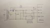
So I'm thinking of building a supply putting out 9v DC using a 7809 regulator, and for the LED driver supply... I'm not so sure. A regulated supply with 2.4v out off the same source feeding the 7809?

I don't need any additional supply for a radio or alarm as in the application notes, I'm just building a straight forward digital clock.

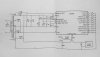
The scanned circuit should hopefully be clear enough but in case it isn't the secondary windings are 7.75v rms CT. The asterisks on the windings refer to 3.5v rms @ 250mA.

Thanks guys. I'm a bit rusty with circuits now as it's been about 40 years since I last built anything. I appreciate your help.

Dave
 

Attachments

  • 3202019215223.jpg
    3202019215223.jpg
    352.5 KB · Views: 128
Bear in mind you need an AC feed for the clock (which comes off the top of the transformer in the diagram) - I would suggest you use a dual output transformer (these are commonly available, probably more so that single output ones) 8-0-8 would be nice, but you might have to settle for 9-0-9. Then for the VLed voltage, use a switch mode regulator to drop the DC output generated from the transformer. The clock AC feed would simply come from the top of the winding as originally.

You can buy tiny adjustable switch-mode regulator modules from Banggood etc. for peanuts.

You could use a second regulator module to get the main supply down to where you're happy as well.
 
Further to Nige's comments, the 50/60 hz input pin on the clock is used internally for keeping the time, so you need Ac.
 
Many years ago, I rebuilt a clock radio that had a transformer like that. The transformer had blown when the clock was connected to 415 V.

As most of the power was taken from the lowest voltage for the LED supply, I found a transformer with a centre tapped secondary, and wired that up as in your diagram to the LED supply.

I then connected the transformer outputs to voltage multipliers, using electrolytic capacitors and diodes, to give the higher voltage for the clock electronics / radio. It was basically two of these:-
http://www.creative-science.org.uk/mult/2multa.gif
with one of each phase of the transformer secondary so that the output was still full-wave rectified. If you connect the anode of D1 to the opposite phase, not to ground, you get more voltage out.

For the high voltage AC, I used a separate, tiny transformer. It was something like on of these:-
http://uk.farnell.com/block/vb0-35-2-9/transformer-0-35va-2-x-9v/dp/1131609 but it had flying lead connections. You can now get toroidal transformers like this:-http://uk.rs-online.com/web/p/toroidal-transformers/2786762/

It is highly unlikely that the 50/60 Hz input has to go negative for the clock to count the frequency. You could just have a pull-up to the +ve supply, and a transistor to ground switched by the ac output of the transformer to give you a waveform that would be fine for timing. That would avoid the need for a second transformer.

As an alternative, find a transformer that will directly supply the clock electronics, the radio and the 50/60 Hz input, and then use a buck regulator to provide the lower voltage for the LEDs.

Another alternative would be to find a toroidal transformer for the clock electronics etc, and make sure that it is one with a hole in the middle. Then wind some turns of wire around through the middle to give you the voltage you need for the LEDs. I guess you will get 0.2 V per turn, but you will have to measure it. If you are taking as significant proportion of the transformer power from the extra winding, make sure that the turns are spread evenly around the transformer.

You can full-wave rectify with schottky diodes to minimise the number of turns that you need.
 
Thanks for the suggestions, some good ideas there. As the clock case is small I'd ideally like to supply the power from an external supply. I was considering using a plug pack with an AC output and doing the dc conversion where the clock module is. Probably a lot tidier than building a second external supply.

I like the idea of the switch mode modules for supplying both the clock IC and Vled. That sounds simple but could I feed both modules off one AC output rather than a center tapped supply?
ie. rectify the ac, use two switch mode regulators with the negative out on each connected together for Vss, with one regulator set to 9v and the other 2.4v, and a 100k resistor connected to the AC which feeds the 50/60 Hz on the clock. Would that work?

How reliable do you think those regulator modules might be? Would I get maybe 20 years out of them or would they likely fail after a few years?

I also like the idea of using a toroid and winding another secondary for the 2.4v, another good option I could use should the first not work.
 
I like the idea of the switch mode modules for supplying both the clock IC and Vled. That sounds simple but could I feed both modules off one AC output rather than a center tapped supply?
ie. rectify the ac, use two switch mode regulators with the negative out on each connected together for Vss, with one regulator set to 9v and the other 2.4v, and a 100k resistor connected to the AC which feeds the 50/60 Hz on the clock. Would that work?
That should work. I suggest you post a circuit diagram.

How reliable do you think those regulator modules might be? Would I get maybe 20 years out of them or would they likely fail after a few years?
If you don't have the regulators running hot, they should last for ages. The main type of component that degrades is electrolytic capacitors, and if you keep them cool, and have larger capacitance than you need, 20 years isn't difficult.
 
This is the circuit I've drawn up today using the suggested regulators from Banggood.

I realise I probably should have drawn it showing the 0.01uF connected to the 0v transformer secondary line rather than the regulator 0v output. I ran out of space to fit it in.

I'd possibly add a couple of electrolytic caps across the regulator outputs too.

I have a plug pack with 9v AC 1A output which is more convenient than fitting the transformer into the small clock case. I also have a 12v AC 1.5A unit but I think the 9v one should be okay.

Hopefully the switch mode regulators will have a common earth on the in & outputs.

Do you think this would be okay?
 

Attachments

  • 3222019212744.jpg
    3222019212744.jpg
    304.6 KB · Views: 109
I would suggest that you use a full wave rectifier. I can't see any reason why not.

I agree with Nigel that 100 uF is too small, but I would suggest even larger than 1000 uF. If you are taking 1 A, and full wave rectifying at 50 Hz, then with a 10,000 uF capacitor you will get about 1 V of ripple.
 
I would suggest that you use a full wave rectifier. I can't see any reason why not.

That was my initial thought - but I'm not happy about no earth reference for the AC clock pulses.

Which was why I initially suggested a 9-0-9 transformer.

I agree with Nigel that 100 uF is too small, but I would suggest even larger than 1000 uF. If you are taking 1 A, and full wave rectifying at 50 Hz, then with a 10,000 uF capacitor you will get about 1 V of ripple.

Consumption shouldn't be too bad, as he's using switch-mode regulators, so dropping down to feed the LED's should lower the current considerably.
 
Thanks again for the suggestions. I thought that the half wave rectifier and 100uF electrolytic might be okay as the original design application notes used this, although I agree the 1000uF would be better. The typical current consumption at 9v is around 5mA plus the current drawn by the regulators. The current drawn by the LEDs is around 300mA. The original circuit diagram had no filtering on the VLED supply at all so possibly the 1000uF may be okay. It might be a case of trial and error.
A 9-0-9 transformer would be the way to go but building a separate AC supply is not ideal. I could try using the half wave rectifier and if not suitable would have to consider falling back to the 9-0-9 supply.
 
Thanks again for the suggestions. I thought that the half wave rectifier and 100uF electrolytic might be okay as the original design application notes used this.

No it didn't, it used a full wave rectifier, which means you can use a much smaller reservoir capacitor, which again, was why I suggested a 9-0-9 transformer.
 
Yes, you're right, I missed that. Okay looks like I'm looking for a 9-0-9 transformer. I should be okay from here on, my original question was mainly how to supply the 2.4v to the LEDs and those cheap regulator modules are perfect.
Dave
 
Status
Not open for further replies.

Latest threads

New Articles From Microcontroller Tips

Back
Top