Continue to Site

Welcome to our site!

Electro Tech is an online community (with over 170,000 members) who enjoy talking about and building electronic circuits, projects and gadgets. To participate you need to register. Registration is free. Click here to register now.

  • Welcome to our site! Electro Tech is an online community (with over 170,000 members) who enjoy talking about and building electronic circuits, projects and gadgets. To participate you need to register. Registration is free. Click here to register now.

Look at this schematic - Need help please

Status
Not open for further replies.

eightwgt

New Member
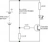
Here is the schematic I am making for a water activated switch - for a watrer level....

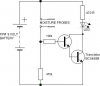
Any suggestions as to how to make it SUPER sensitive >>> I will have one probe contact at the bottom of an acrylic tube - the other ( a needle) set in a rubber fixture....... when the water touches the point of the needle I want the led to light up at the SLIGHTEST contact............

ANY HELP HERE ????
 

Attachments

  • waterschem.jpg
    waterschem.jpg
    13.4 KB · Views: 3,933
Two ways to increase sensitivity
1) Increase the value of R2. 1.2K is very low.
2) Use darlington configuration making use of two BC548's. The base of first transistor is connected to the biasing network while its emitter is connected to base of other transistor. Collectors of both transistors are tied together and used as if it is a colletor of single transistor.
 
KINJALGP

Thanks - I kinda unerstand what you are saying - I am VERY new to this and only have a VERY basic understanding of it ..... What would be more sensitive ?? And what size resistor would you use instead of the 1k2 ??

Darlington configuration ? Is this some standard ??

I thank you for your help..... very much appreciate it.

Tom
 
Yes, darlington is a standard transistor confuguration wherein you can get very high current gain. The output curent of this configuration is Hfe^2 (square). Thus even for very low input current, you get high cuurent output to drive the LEDs.

Instead of 1.2k use 47k or even try 120k resistor.
 
Ok next question....... Do you know a compatible transistor that radio shack sells ?? they do not have the transistor i have on the schematic and id like to make it this weekend
Also, would I have to change anything ?
 
Look at this link - its a Radio Shack Data sheet for a 2N2222A Transistor

How can I use it and get a good result ??

**broken link removed**
 
The 2N2222 is an OK replacement. For your purposes, basically any NPN small signal transistor is OK.
 
Just one problem: if the water is destillated: no conduct. Drinkwater is conductive, but the positive electrode always go to solution (corroded).
For direct sensing use AC to avoid the corrosion.
 
Thanks for all the input so far everyone - I appreiciate the help. To let you know what I am doing with this thing - I am building a machine - a CNC machine and going to use it to level the table out. I need it level to within .002"-.004" Thats why I need the sensitivity so when the conductor (needle) contacts the waters surface it instantly reads. The 'tube' shown is mounted on a caliper base, which in turn is mounted to a C-clamp... so I adjust the height of the conductor-electrode-needle (whatever ya wanna call it) and when I get it set I have a solid refferance in which to measure from.

Now I just gotta figure this thing out..... any comments yet on the transistor from radio shack ? I looked at them and they had differant values than the one I noted on the schematic...... so I dont know how to modify it.... So that brought me here....

Thanks again for all help and comments

Tom Mitzlaff
www.mitziskiffs.com
 
To help with the conductivity of the water, I can add an algea killer (pool product) to water which is a copper solution, or I can add salt..... This is only a temporary tool Ill use once in a while so corrosion is not a problem
 
"they [the transistor from radio shack] had differant values than the one I noted on the schematic"
The transistor labeled "BC5488B"?
A simple search shows me such a transistor does not exist.
Most likely it is supposed to be the BC548B.
This is a common NPN that is very much the same as the 2N2222A.
What are the different values that you noted?
I noted I had one of the 2N2222A transistors from Radio Shack on hand.
Since this is such a simple circuit I quickly tested it.
I also replaced the 1.2K [one thousand two hundred] ohm resistor
with a 47K [forty seven thousand] ohm resistor as many others here have reccomended to you.
Using common tap water [mine has 1 million 400 thousand ohms resistance per inch]
the slightest touch of the probes to water caused the LED to light to it's full brightness.
Go buy the RS transistor, they are all of 69 cents.
 
You can use any NPN transistor in darlington-pair.
 

Attachments

  • waterschem_898.jpg
    waterschem_898.jpg
    14.7 KB · Views: 3,789
You guys are awesome...... I really find it great I can get on here and get this kind of help......

Can I ask you a question.... Whats the more sensitive swith - the Darlington confighuration or what you tested Mofest ?
I have to go back to Radio Shack and get a 470 resistor.... thought I had one......
Question - maybe a dumb one..... what type of LED did you use ? I purchased quite a few.....
Also.... what watt resistors did you try Mofset 1/4?

Thanks again for your help guys - it truely is appreciated.

Tom M
 
bang on - bang off, no sensitivity involved
I haven't built Sebi's circuit, but knowing his work I'm sure it works.
resistors 1/4 watt, LED a piece of junk I had laying around
 
Mofset

Thanks again.....

i just got an assortment of resistors... trying to figure out which is the 470 !!

Thanks
 
I need to give up electronics/....... I cannot seem to get this right.... It still doesnt work.

My LED is a 2.6V, 28 mA, 10 mcd.... is that the problem ?
 
Possibly, you may also want to consider stepping down the voltage to about 3v, If you have an adjustable power supply, drop the volatage to 3V then test the LED alone, you could have easily blown it, I know I've popped a whole lot of them.

Also if you still have any of the packages make sure none of them say "Bi Polar" if not, one by one flip everything but the transistor, (save this one for last) and test each different position, after you test one, flip it back and try the next.

It's very easy to miss this one.

But I'd first try testing the LED, if it comes on, check all your connections, make sure you didn't do something trivial like connecting a resistor horizontally on your breadboard.
 
I just took a long hard look at your schematic, and two things didn't seem right, the placement of the transistor, and the positioning of the LED.

For some reason the transistor just doesn't look right, I have no idea why, and consider moving the resistor and LED to before the probes.
 
What ya mean hooking it up horizontally ??

I cant find anything that says bi-polar...

What color bands are on a 1K resistor...

By the way - all resistors are 1/4 watt
 
Status
Not open for further replies.

Latest threads

New Articles From Microcontroller Tips

Back
Top