Electro Tech is an online community (with over 170,000 members) who enjoy talking about and building electronic circuits, projects and gadgets. To participate you need to register. Registration is free. Click here to register now.
Welcome to our site! Electro Tech is an online community (with over 170,000 members) who enjoy talking about and building electronic circuits, projects and gadgets. To participate you need to register. Registration is free. Click here to register now.
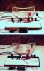
okay, well then I guess my first Idea wouldn't matter... hooking up a component on a breadboard horizontally is a no-no, it'd be like making a PCB with wiring like this ---0----0--- and we all know that doesn't work
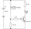
anyway, just keep messing with it, and 1K is Brown/Black/Red fourth stripe is the tolerance if yours has one, if not, doesn't matter.
Looking at the transistor from the TOP-its shaped like a D right... So, you hold it looking at the top so the arc is too the right or as the letter D is written, the Emmiter wire would be thetop wire correct ?? The Middle is the base obviously, and the collector would be the bottom wire...... Im just makin sure I didnt hook up the transistor backwards... if I did would it have blown the transistor ?? I am using a 9 volt battery by the way -
Feels great ! I am a happy camper. I was not about to give up ! The application I am using it for works very well and the circuit is perfect although the only problem is the tip of the conductor probe is getting eaten away a little at a time so that makes for constant adjusting.... If I lowered the voltage requirement can I still make it as sensitive ? Now the Darlington would be a good canidate right ? Doesnt it help increase the voltage so I could drop the voltage going into the probe...... I wonder if it would still get eaten up as bad ? I started turning it off as soon as it contacted the water and I got a reading.... that helps.
As far as the water level I made... Its a little crude but accurate over a 10' distance to about .002"-.003". I took multiple readings and averaged out the differance measuring with calipers, and it could be improved to a consistant .002" if I tighten everything up so measuring can be more consistant....
Use stainless steel probes. They won't have any problem of rusting or other reactions. I have used in my water level controller and its still working since past 6 years.
Or you could use aluminum, it's already got an oxidized coating and water doesn't damage it, that's why it works so well with soda, I mean hell, soda is basically a weak acid and it doesn't even scratch aluminum, and even if it does get a scratch in the aluminum past the oxide coating, exposing it to air for roughly 30 seconds will put a new one over the scratch.
This site uses cookies to help personalise content, tailor your experience and to keep you logged in if you register.
By continuing to use this site, you are consenting to our use of cookies.

") and we all know that doesn't work
and we all know that doesn't work