Continue to Site

Welcome to our site!

Electro Tech is an online community (with over 170,000 members) who enjoy talking about and building electronic circuits, projects and gadgets. To participate you need to register. Registration is free. Click here to register now.

  • Welcome to our site! Electro Tech is an online community (with over 170,000 members) who enjoy talking about and building electronic circuits, projects and gadgets. To participate you need to register. Registration is free. Click here to register now.

Long tailed pair collector current mirror

Status
Not open for further replies.

Quasar999

New Member
Hello
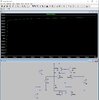
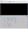
i want to understand how work a differential amp with a mirror current section and i did the following pspice simulation. Is really weird cause the mirror current at the top keep the same current in the Q1 e Q2 have both the same base current and is not clear how change the Vce in them.
From the simulation output voltage seems to have a good gain but is not well biased. What do you think?
 

Attachments

  • Draft4.asc
    1.8 KB · Views: 183
  • DiffAmp.jpg
    DiffAmp.jpg
    205.5 KB · Views: 249
You .asc file (LTspice, not Pspice.) is different that shown in the .jpg file.
 
the output of a diff amp is in the form of current, not voltage. to get voltage gain out of it, you need a voltage amplifier stage to transform the current variations back into voltage variations. this would be a PNP transistor with the emitter tied to the +vcc rail, the base to the diff amp's out-, and a 20k or so resistor from the collector to the -vcc rail... you also do not need 0.8v dc bias on the diff amp inputs, as the emitter current source will float the emitters slightly negative...
 
Updated Schematic. Added the pnp at the output but still the result are weird.
 

Attachments

  • Sch2d.jpg
    Sch2d.jpg
    207.6 KB · Views: 226
  • Draft4.asc
    1.9 KB · Views: 193
Is this what you expected?
The circuit has a very high gain (over 80,000 to Out2), so is sensitive to very small offsets in the circuit (apparently about 1mV referred to the input here).

1617853110220.png
 
Last edited:
this would be a PNP transistor with the emitter tied to the +vcc rail, the base to the diff amp's out-, and a 20k or so resistor from the collector to the -vcc rail
The PNP's form a current-mirror differential to single-ended converter and require no resistors.
 
What do you think?
Looks good.
But note that the simulation uses identical (matched) transistors, while the real circuit with discrete parts will have offsets due to the normal mismatch been transistors of the same part number.
 
Status
Not open for further replies.

Latest threads

New Articles From Microcontroller Tips

Back
Top