Continue to Site

Welcome to our site!

Electro Tech is an online community (with over 170,000 members) who enjoy talking about and building electronic circuits, projects and gadgets. To participate you need to register. Registration is free. Click here to register now.

  • Welcome to our site! Electro Tech is an online community (with over 170,000 members) who enjoy talking about and building electronic circuits, projects and gadgets. To participate you need to register. Registration is free. Click here to register now.

Logitech x-540 6 channels amplifier

Status
Not open for further replies.

ro0ter

New Member
Hi everyone,

I just got a Logitech X-540 amplifier which does not work right. It is a 110V amplifier which was in a 220V-to-110V power converter while there was a power fluctuation (this is my explanation).

Symptoms: when turned on it is silent for like 2-4 seconds and then an intermittent low-frequency high-volume sound starts buzzing in all the speakers.

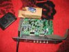
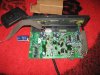
I opened it and i saw a pumped-up capacitor (the one in the power supply stabilizer, after the transformer, it is a 25V 6800uF capacitor) and also a resistor (a really heavy one) but the resistor is so fried out that you can`t see any colors, only the blown coil.

Please, can anyone help me with this?

I will also upload a few pictures of the amplifier board.

Thank you very much, I really appreciate :)
 

Attachments

  • dorin 001.jpg
    dorin 001.jpg
    2.5 MB · Views: 7,739
  • dorin 002.jpg
    dorin 002.jpg
    2.4 MB · Views: 7,135
The cap should be easy to replace that resistor not so much if you can't find a schematic or find someone else that has the same unit to compare it to.
 
I'm looking everywhere for a Schematic.
Here is the Owners Manual.
 

Attachments

  • Logitech x-540_Owners_Manual.pdf
    673.2 KB · Views: 2,811
Thanks guys for your quick replies, the capacitor is not a problem for me, i just wrote about it because i thought it might ring a bell to someone.

Thanks hotwaterwizard for the schematics of the driver circuit.

Still what is extremely strange is that each resistor end is connected to a capacitor end. very funny. check out the R700 next to the C700 ( second attached picture of this thread )

Also I would need to make it work with european voltage... How will a 110-to-??? volts transformer act under 220 volt? double the output tension? (i don`t remember right now the output tension of the transformer, will get back with that later today)

best case scenario - i would need a high-amperage power rectifier, right?


About the fried resistor - is there anyone that has clue?

thank you so much :)
 
Thanks guys for your quick replies, the capacitor is not a problem for me, i just wrote about it because i thought it might ring a bell to someone.

Thanks hotwaterwizard for the schematics of the driver circuit.

Still what is extremely strange is that each resistor end is connected to a capacitor end. very funny. check out the R700 next to the C700 ( second attached picture of this thread )

Also I would need to make it work with european voltage... How will a 110-to-??? volts transformer act under 220 volt? double the output tension? (i don`t remember right now the output tension of the transformer, will get back with that later today)

Double the voltage, serious problems.

It will pretty well instantly destroy the amp - that could be what's happened?, it would blow the capacitor like it has, and the amplifier chips going S/C (or some more capacitors) could have blown the resistor.

best case scenario - i would need a high-amperage power rectifier, right?


About the fried resistor - is there anyone that has clue?

You need to follow where it connects to, to give us a clue as to what it does.
 
Nigel, I wrote in my first post that there was a power fluctuation on the mains while this sound system was plugged in a 220-to-110 voltage converter. unfortunately i guess that the voltage converter was some low-end piece of crap and didn`t do a good job in the fluctuation (had no limiter and maybe the tension raised over 120 volts on its output).

That might have happened. The sound system was NEVER plugged in the 220 mains directly.

about "adapting the sound system to feed directly from the 220v mains" - i only asked what happens if i run under 220 volts a transformer designed to work under 110 volts; for example 110-to-64 transformer, if i plug it in 220 - would it fry or would it output 128 volts? what would be the current? i guess half but i never did that, that`s why i am asking.

thanks
 
Nigel, I wrote in my first post that there was a power fluctuation on the mains while this sound system was plugged in a 220-to-110 voltage converter. unfortunately i guess that the voltage converter was some low-end piece of crap and didn`t do a good job in the fluctuation (had no limiter and maybe the tension raised over 120 volts on its output).

That might have happened. The sound system was NEVER plugged in the 220 mains directly.

about "adapting the sound system to feed directly from the 220v mains" - i only asked what happens if i run under 220 volts a transformer designed to work under 110 volts; for example 110-to-64 transformer, if i plug it in 220 - would it fry or would it output 128 volts? what would be the current? i guess half but i never did that, that`s why i am asking.

The voltage output would double, as a consequence the current drawn would double, things in the amplifier would 'blow up' and the transformer would die in a few seconds.

I see it all the time on American gear people bring over :D

EDIT:

Just been looking at the datasheet for the chip, it's maximum voltage is 22V, and the capacitor is rated at 25V - I would suggest that the supply has gone higher than 25V, blowing the capacitor, and quite possibly taking the chip as well.
 
Last edited:
The voltage output would double, as a consequence the current drawn would double, things in the amplifier would 'blow up' and the transformer would die in a few seconds.

I see it all the time on American gear people bring over :D

It`s not the case here.

Anyway, if someone trips over some schematics of a 50-watt, 6-channel-amplifier please drop me a line.

Thanks, people!
 
The resistor is probably just a bleeder to discharge the caps when the equipment is turned off. The value is not critical, just calculate an RC time constant you are comfortable with and get resistor of a proper resistance and wattage rating and you will be fine. It probably was only rated for double its normal dissipation, and popped when the higher voltage was applied across it.
 
The resistor is probably just a bleeder to discharge the caps when the equipment is turned off. The value is not critical, just calculate an RC time constant you are comfortable with and get resistor of a proper resistance and wattage rating and you will be fine. It probably was only rated for double its normal dissipation, and popped when the higher voltage was applied across it.

Sorry, but they don't fit bleed resistors on low voltage equipment, in fact they often don't bother even on high voltage equipment.
 
I disagree with Nigel on bleader resistors. But, I think yout resistor serves a different purpose. It may be a way of stabilizing the voltage regulator in the power supply or stopping the switch from making a popping sound when the power is turned on.
Look at these schematics from a Marantz, There are bleader resistors all thru the schematic.
 

Attachments

  • 2.gif
    2.gif
    193.3 KB · Views: 8,801
  • 7.gif
    7.gif
    181.5 KB · Views: 3,997
I disagree with Nigel on bleader resistors. But, I think yout resistor serves a different purpose. It may be a way of stabilizing the voltage regulator in the power supply or stopping the switch from making a popping sound when the power is turned on.
Look at these schematics from a Marantz, There are bleader resistors all thru the schematic.

I suggest you reconsider what you think a 'bleeder' resistor is, and does - I see none in that diagram?. There are two large 10,000uF 50V capacitors, any bleeder resistors would be across them - there are none.
 
You win Nigel
How about this application? There are Emitter Resistors etc in this power supply that are 2watt resistors not bleaders.
 

Attachments

  • 13.8v 20A Linear Power Supply.gif
    13.8v 20A Linear Power Supply.gif
    69.7 KB · Views: 3,261
Last edited:
LOL the prize is you taught an old dog a new trick.
Don't bark at someone before you can see them putting food in your bowl.
 
I barked at you before I saw the bowl with cats around it. As you know the Cats will tear that Old Dog up.
 
Status
Not open for further replies.

Latest threads

New Articles From Microcontroller Tips

Back
Top