Continue to Site

Welcome to our site!

Electro Tech is an online community (with over 170,000 members) who enjoy talking about and building electronic circuits, projects and gadgets. To participate you need to register. Registration is free. Click here to register now.

  • Welcome to our site! Electro Tech is an online community (with over 170,000 members) who enjoy talking about and building electronic circuits, projects and gadgets. To participate you need to register. Registration is free. Click here to register now.

Logic Protection Circuit

Status
Not open for further replies.

crashmeplease

New Member
I am looking for ways to protect/disable a logic circuit both during power up, and possibly if the micro controller enters an invalid state, even if unlikely.

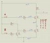
The best thing I could think of for simplicity was using transistors as logic gates, thus when one input is high and the other low (driven by the micro) then enables my logic circuit (low output). See attached.

While the idea is basic, it serves that the inputs must be in a predetermined stage to enable the logic circuit. I was thinking of trying to add in a little RC network stage to delay from power on.

Are there any other simple ways to do this? If I just control the logic enable directly with a single micro output, I can see there could be times during power on/reset/programming when the logic circuit could possibly be enabled. Requiring both a high and low pin to enable the logic circuit should add an extra layer of safety?

Although if there was a problem with the micro once it was initialised, potentially the predetermined on state could remain on, however unlikely?

TIA :rolleyes:
 

Attachments

  • LPC.jpg
    LPC.jpg
    219.3 KB · Views: 195
Hi,

While understanding your view, it does seem to say little for whatever micro you are using, properly used they run for years without failure.

They have loads of power up / brown out controls etc, and you can add futher hardware / program code so they actively monitor their own power rails.

You could even use a button cell/s as backup power to the micro for a few seconds so it could turn off your logic circuits when the main power fails etc.

Don't forget, the more circuitry you introduce, so the failure rate increases !
 
I have seen PIC port pins go through some strange gyrations as the PIC boots up or after the MasterReset is asserted. It has to do with the default state of Data and Tris registers with pins that will eventually become outputs in a known state start out as high-impedance inputs.

The specific states and how long the pins stay in those states can be partially controlled by executing initialization code as early as possible in the boot-up sequence.
You can also add weak pull-down/pull-up resistors to the inputs of transistor drivers so that the first time they turn-on for real is after the boot-up sequence, and only when a "real" i/o instruction to turn them on is written to the port register.

I also dealt with this issue in using a Parallel-Port on a PC to control external logic. During PC Boot-up, the port pins go crazy, probably because the bios writes various patterns to the PP as a diagnostic? Any way, to prevent various loads from turning on/off during boot-up, I found some combinations of pins which never occured during boot-up, and used those to assert the real functions I wanted.
 
LOL this is why MS decided to discontinue parallel port.
it is gone since Vista, Win Server 2008,
though i am still able to output data, and cause a LED to flicker!

it is only documentated very marginally.

I think they want everyone to use USB.
 
OP

you could maintain a CMOS or even NE555 oscillator (pray it will start up correctly but most likely these circuits always start up), and then, have a mono-flop together with an AND,

so you can hook a line from the PIC, and pulse this line with some 100 Hz (via software).

if this signal fails to appear (hence the monoflop) after a small while of maybe 100 to 200ms, you get the error condition!
if the signal disappears, you also get the error condition.

if you can ensure the uC starts up, just use the provided watchdog (but the circuit I describe also covers non-startup).

I hope you can understand it/build it.
 
There are many watchdog timer chips available that will do what you need. 8 pin parts with many options. Just do a search at Maxim or Dallas semi to name a few. Here is a start of your search.

**broken link removed**
 
Thanks for the input so far. I am using an AVR btw, and yes it's connected to the parallel port. But this is only for development, and the finished item will be stand alone.

Some backgound; I am driving an LED matrix display, and the last thing I would want is for some erroneous logic state to appear on the shift registers during startup, and to turn on and lessen the life matrix displays, and as I have 10 of them, and potentially put a lot of continuous current through my row drivers. To make life more interesting they are RGY displays, so twice as many LEDs.

Should I just trust the micro here and assume everything will start up correctly? I have never built anything on this scale before and want to account for most eventualities..

OP

you could maintain a CMOS or even NE555 oscillator (pray it will start up correctly but most likely these circuits always start up), and then, have a mono-flop together with an AND,

so you can hook a line from the PIC, and pulse this line with some 100 Hz (via software).

if this signal fails to appear (hence the monoflop) after a small while of maybe 100 to 200ms, you get the error condition!
if the signal disappears, you also get the error condition.

if you can ensure the uC starts up, just use the provided watchdog (but the circuit I describe also covers non-startup).

I hope you can understand it/build it.

Hmm I like this idea, I think I remember seeing something like this before, but it didn't click what it was at the time, basically a bunch of CMOS NAND gates with a few resistors and capacitors, will have to investigate this.


There are many watchdog timer chips available that will do what you need. 8 pin parts with many options. Just do a search at Maxim or Dallas semi to name a few. Here is a start of your search.

**broken link removed**

Thanks but I was hoping to get away from buying specialist ics, hence the simple approach. I have access to boxes of basic components, and some of the more common logic ics at my disposal.
 
Quote:
Originally Posted by Mikebits
There are many watchdog timer chips available that will do what you need. 8 pin parts with many options. Just do a search at Maxim or Dallas semi to name a few. Here is a start of your search.

**broken link removed**


Thanks but I was hoping to get away from buying specialist ics, hence the simple approach. I have access to boxes of basic components, and some of the more common logic ics at my disposal.
--------------------------------------------

These are not special IC's, rather very common.
 
Last edited:
Some background; I am driving an LED matrix display, and the last thing I would want is for some erroneous logic state to appear on the shift registers during startup,

The solution is to keep the registers in reset during power up. A watchdog chip can accomplish this function as it has user settable reset delays.
 
you do not write the matrix size, or how you drive the matrix.

I'd suggest you use a lower voltage, 3 volts or so, and just test what happens.

the PIC circuits I have do not get a problem in case of lockup, the display lights 2x time as bright, but does not burn out.

you could add capacitor to the /OE to get a startup delay,
and then give a signal from your AVR microcontroller.

there is also a small chance that the uC does not start up correctly, but outputs signals, also this can be caused by program errors/lockup.

for this purpose the monoflop.
 
Status
Not open for further replies.

Latest threads

New Articles From Microcontroller Tips

Back
Top