Continue to Site

Welcome to our site!

Electro Tech is an online community (with over 170,000 members) who enjoy talking about and building electronic circuits, projects and gadgets. To participate you need to register. Registration is free. Click here to register now.

  • Welcome to our site! Electro Tech is an online community (with over 170,000 members) who enjoy talking about and building electronic circuits, projects and gadgets. To participate you need to register. Registration is free. Click here to register now.

Logic Level translator

Status
Not open for further replies.

bryan

Member
All:

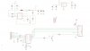
Would appreciate some help on this. I am following the attached schematic which uses a 74xx245 (Octal 3 state non inverting). I can only assume the purpose of the 74xx245 is to act as a logic level translator to convert the incoming signals (pic micro)from 5v to 3.3 v for a LCD.

I have hooked up the schematic with VDD at 3.3v. When testing the A side on my scope I am seeing voltages of 5v which is correct as this is the pic outputs, but the B side is returning 4.3 volts to the LCD. Should the B side not return signals of 3.3volts, otherwise what is the point. Perhaps I am missing something in the schematic and/or it is not working properly?. I assume the 4.3v is simply the voltage drop from the internal circuitry of the xx245.

Seems to me the 74xx245 is the wrong choice of a translator and something else would be better suited, but I see it used in this particular arrangment before.

Comments/suggestions

Cheers
 

Attachments

  • translate.jpg
    translate.jpg
    42.4 KB · Views: 1,184
Wonder why a transceiver would be needed. It is for a Arduino project. the mcu is connected to a Nokia LCD display. Could it be to protect the mcu outputs, if not a level shifter I wonder what is protecting the LCD inputs that are rated for 3.3 volts?
 
Wonder why a transceiver would be needed. It is for a Arduino project. the mcu is connected to a Nokia LCD display. Could it be to protect the mcu outputs, if not a level shifter I wonder what is protecting the LCD inputs that are rated for 3.3 volts?

hi Bryan,
Which version of the 74 are you using, is it the 'AC', 2Vdd to 6Vdd version...?
 
I am using the HC version 74HC245, could that be the problem?

hi,
Just been comparing the d/s, they seem to have a similar operating range.?

I suspect the designer of the circuit is trying use the transceiver as a 5V/3.3V level shifter.??

Do you have a link to the design site.?
 
Thanks for the reply. Yes I suspect that is what the design is for, as I have seen it been used in Arduino projects before for this purpose, but I can't get it to work. A friend has suggested using just a 74HC4050 as it appears to be designed for this purpose.

The project is the Arduino Reef Angel Controller. The schematic is near the bottom of the page Eagle Files -->LCD Board.

**broken link removed**

The 4050 will translate down but not up, also its not bidirectional with hiZ option.
 
Downloaded that info, but I cannot open the*.sch file, I dont have Eagle....
 
Here is the schematic of the LCD board. The header SV1 is a connector to a AVR outputs.
 

Attachments

  • Untitled.jpg
    Untitled.jpg
    121.8 KB · Views: 945
hi,
It definitely looks as though as he is trying to level shift between 3.3V and the 5V logic levels.

I have never tried that method but i would suspect that you would get the problems you are seeing.
The 5V levels from the PIC are driving thru the 74HC which is powered by 3.3V and are appearing at the LCD much higher than 3.3V.

Do you know if any one else has managed to get this circuit to work.??
 
Last edited:
hi Bryan,
Looking at the circuit shows that the bi directional function of the 74HC transceiver is not being used. the direction line is tied to Vdd
So it will be possible to use a HEF4050 as a translator. OK

For reference in logic levels look at this pdf
 

Attachments

  • 3_3vto5vAnalogTipsnTricksBrchr.pdf
    952.8 KB · Views: 359
Thanks, yes have seen that publication before. Ended up using a resistor voltage divider as a test. Worked fine, but did notice some "rounding" of the signals at higher frequencies, the LCD still worked properly though.
 
Thanks, yes have seen that publication before. Ended up using a resistor voltage divider as a test. Worked fine, but did notice some "rounding" of the signals at higher frequencies, the LCD still worked properly though.

hi Bryan,
You should get back to the original author of that design and advise him of the changes that you had to make, so that he can correct the schematic, it may help other builders...
 
Well I did point out to the author that it does not appear to work as designed. Response back was the xx245 was used as a shift level translator 5v->3.3v, but no response back further on why it doesn't work.
 
Status
Not open for further replies.

Latest threads

New Articles From Microcontroller Tips

Back
Top