Continue to Site

Welcome to our site!

Electro Tech is an online community (with over 170,000 members) who enjoy talking about and building electronic circuits, projects and gadgets. To participate you need to register. Registration is free. Click here to register now.

  • Welcome to our site! Electro Tech is an online community (with over 170,000 members) who enjoy talking about and building electronic circuits, projects and gadgets. To participate you need to register. Registration is free. Click here to register now.

Log Data using pic16F877A

Status
Not open for further replies.

williB

New Member
some of you will remember that i made my own pic programmer
its based on a SPI like interface that hooks into the pc through the ISA bus , and is controlled by a pascal program running under DOS.
the beauty of the system is the control you have over the signals being sent to the pic .
i will post the schematic , and the pascal source program , if there is interest

Well i just ended two days of debugging of the program which works verywell now.
it doesnt program the config word , yet.
and you have to strip off the first and last lines of the Hex file before running the pascal program. but i dont expect much interest in programming a pic by this method , but the spi interface is cool , and i've used it to run a Microchip MCP3004 four channel a/d converter, as well as program the pic.

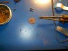
i have been assembling sensors like the hall effect sensor found in any cd rom drive motor.(each motor has three)
with this sensor i am going to (and have) measured AC current and Frequency(RPM) from a Permenant magnet alternator.
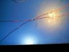
i have another input to the data logger that i want to use , it is a hall effect switch ( from a pc powersupply fan ) with the armeture removed and the hall switch & the circuit board left intact, this will display wind speed . I have allready used this setup hooked to a scope , and with 5v applied to the circuit board , a 0-5v digital signal pops out whose frequency varies with the applied wind speed .
i would also like to measure pressure , there was/is a USB Mail scale from rat shack for sale on ebay, but i'll wait on that .
i would like to have the F877A talk to my laptop through the serial port , and have the laptop collect and store all the data , for later analysis.
i dont have any immediate questions ,but i know i will have many, i just thought i would let yall know what i've been up to.
 
Last edited:
williB said:
some of you will remember that i made my own pic programmer
its based on a SPI like interface that hooks into the pc through the ISA bus , and is controlled by a pascal program running under DOS.

The entire idea still sounds completely bizarre? - building an ISA card programmer?, as does writing for DOS in 2006?. As you're using Pascal I would suggest moving to Delphi and writing under Windows instead?. I moved PicProg from Turbo Pascal under DOS to Delphi 1.0 under Windows 3.0 a LONG time ago (and renamed it WinPicProg), basically as a learning experience for Delphi.

the beauty of the system is the control you have over the signals being sent to the pic .
i will post the schematic , and the pascal source program , if there is interest

Well i just ended two days of debugging of the program which works verywell now.
it doesnt program the config word , yet.

It's easy enough on the 877A, the programming datasheet explains it - and your existing code contains 99% of what is needed.

If it's of any interest?, version 1.0 of PicProg was written in Turbo Pascal from scratch while I was waiting for a programmer PCB to arrive from Dontronics in Australia - probably about four days?. This was actually why PicProg (and then WinPicProg) includes a disassembler, I had so much time left while I was waiting that I wrote a disassembler to go with it. This was ONLY for the 16C84, which was the only EEPROM based PIC at the time.

and you have to strip off the first and last lines of the Hex file before running the pascal program.

This sounds totally bizarre as well?, why on earth are you having to do that? - just write your Pascal program to do all the processing required.

If it's any help?, WinPicProg reads the entire program into a series of buffers, one for the program, one for the data EEPROM, and one for the config fuses and ID. I don't know if you're doing it that way or not?, but DOS memory limitations tend to make it much easier under Windows - which was why PicProg development stopped while WinPicProg developed further.
 
hi Nigel ,
i'm not really used to this new php that electrotech is now using.
but it is only a text file so here goes .
as you know the first and last lines are not the program itself..
i forget which is which but one of the lines has the config data the other , eh ?, all i know is that without them the program goes in flawlessly , and for me its not that much trouble to remove them.

:020000040000FA
:100000008501860183018316850186018312920191
:10001000003095008316FE30920083120C3097005A
:10002000121583160130850001309B0040309F007F
:10003000831240309F001F148C01202095001D2842
:0C0040008C1C20288C101E081F150800C6
:00000001FF

please note i did say " but i dont expect much interest in programming a pic by this method"
 
the schematic is what i used to make my gauss meter which is what the hall sensor really is .
i got it from a rc site
https://www.rcgroups.com/forums/showthread.php?t=307133

the second pic is the three hall sensors i got out of a cd drive , they are really really small .

the third photo is it with the wires hooked on

since the hall sensor measures magnetic flux it can be used to measure ac current with a ferrite torriod with a slot cut in it and current under test flowing through a wire wrapped around the torroid.
the output of the sensor was .6V peak when i spun my magnets over and under it.
and about .4v peak whem i used the ferrite torroid to measure the current, i havnt calibrated it yet , and i dont know if the output voltage will vary with a different input voltage applied.
 

Attachments

  • u_schematic2.jpg
    u_schematic2.jpg
    25.2 KB · Views: 397
  • IM002293.JPG
    IM002293.JPG
    118.6 KB · Views: 350
  • IM002303.JPG
    IM002303.JPG
    66.6 KB · Views: 349
Wow! that's the longest legs on a spider I have EVER seen? Did you pass the time pulling the other 4 legs off of it? Poor little bugger ;) lol
 
williB said:
hi Nigel ,
i'm not really used to this new php that electrotech is now using.
but it is only a text file so here goes .
as you know the first and last lines are not the program itself..
i forget which is which but one of the lines has the config data the other , eh ?, all i know is that without them the program goes in flawlessly , and for me its not that much trouble to remove them.

:020000040000FA
:100000008501860183018316850186018312920191
:10001000003095008316FE30920083120C3097005A
:10002000121583160130850001309B0040309F007F
:10003000831240309F001F148C01202095001D2842
:0C0040008C1C20288C101E081F150800C6
:00000001FF

please note i did say " but i dont expect much interest in programming a pic by this method"

Yes I know! :D

Code:
:02 0000 [COLOR="red"]04[/COLOR] 0000 FA

:10 0000 [COLOR="red"]00[/COLOR] 8501 8601 8301 8316 8501 8601 8312 9201 91
:10 0010 [COLOR="red"]00[/COLOR] 0030 9500 8316 FE30 9200 8312 0C30 9700 5A
:10 0020 [COLOR="red"]00[/COLOR] 1215 8316 0130 8500 0130 9B00 4030 9F00 7F
:10 0030 [COLOR="red"]00[/COLOR] 8312 4030 9F00 1F14 8C01 2020 9500 1D28 42
:0C 0040 [COLOR="red"]00[/COLOR] 8C1C 2028 8C10 1E08 1F15 0800 C6

:00 0000 [COLOR="Red"]01[/COLOR] FF

The HEX file is explained in the MPASM helpfile, I've spaced it out to make it clearer.

The first byte is how many data words are on the line, this is multiplied by two, so '10' is actually 8 data words.

Next is the address word for the following data, again multiplied by two.

The following byte is the one you're interested in!, it can have three values

00 - normal data line
01 - shows this is the final line
04 - extended address record

So this is the byte you need to check in your program, check the value of it and discard the line if it's 04, process it if it's 00, and if it's 01 finish reading the file.

Next row of words is the actual data, followed by a checksum byte.

Your example HEX file though doesn't include the config fuse data, it's ESSENTIAL that you include that data in your source code, so it's included in the HEX file - it's identified by it's adress location.
 
Last edited:
Nigel will get a kick out of this , the program uses the port function in Pascal to turn on and off , flipflops which in turn allows the user to manipulate the signals going to the PIC or to simulate an SPI interface .

Code:
program asmtohex(indata,outdata,input ,output);
uses crt,dos;
{Const}
{Max = 45;}

Type
Picouttype= array [1..1024,0..14] of integer;
itemtype =Array[1..1024] of char;
Arraytype = Array[0..45] of char;
Var
item:itemtype;
Picout:picouttype;
J:arraytype;
Ch,current:char;
indata,outdata: text;
testrb6,testmclr,dely:longint;
data,
lengthofdataarray,yo1,coun,x11,count,value,temp1,temp,index,step,Rb7I,
pc,z,b,x1,y1,d1,Row,s,Col,x,y:integer;
flag:boolean;


procedure Delay;
begin
  for dely:=0 to 20000 do
   begin
   end;
  end;

Procedure MCLRL;
   begin delay; Port[$379]:=B;{write(' ML');}  delay; end;
Procedure MCLRH;
   begin delay; Port[$378]:=B;{write(' MH');}delay; end;
Procedure RB6H;
   begin delay; Port[$37C]:=B; {write(' 6H');} delay; end;
Procedure RB6L;
   begin delay; port[$37D]:=B;{ write(' 6L');} delay; end;
procedure RB7H;
   begin delay; port[$37B]:=B;{ Write(' 7H ')};delay; end;
procedure RB7L;
   begin delay; port[$37A]:=B;{Write(' 7L ')} ;delay; end;
Procedure ToRB7;
   Begin port[$37E]:=B;delay;delay; end;
Procedure FromRB7;
   Begin Port[$37F]:=B;delay;delay; end;


Procedure StartStopBit;        {required start / Stop Bit}
begin rb6H;rb6L; end;

Procedure Zero;
begin rb6h;rb7l;rb6l;
      rb6h;rb6l;
      rb6h;rb6l;
      rb6h;rb6l;end;

Procedure Zeroend;
begin rb6h;rb7l;rb6l;
      rb6h;rb6l;
      end;

procedure One;
begin rb6h;rb7h;rb6l;
      rb6h;rb7l;rb6l;
      rb6h;rb6l;
      rb6h;rb6l;end;

procedure Oneend;
begin rb6h;rb7h;rb6l;
      rb6h;rb7l;rb6l;
      end;

procedure Two;
begin rb6h;rb7l;rb6l;
      rb6h;rb7h;rb6l;
      rb6h;rb7l;rb6l;
      rb6h;rb6l;end;

procedure Twoend;
begin rb6h;rb7l;rb6l;
      rb6h;rb7h;rb6l;
      end;

Procedure Three;
begin rb6h;rb7h;rb6l;
      rb6h;     rb6l;
      rb6h;rb7l;rb6l;
      rb6h;rb6l;end;

Procedure Threend;
begin rb6h;rb7h;rb6l;
      rb6h;     rb6l;
      ;end;

Procedure Four;
begin rb6h;rb7l;rb6l;
      rb6h;rb6l;
      rb6h;rb7h;rb6l;
      rb6h;rb7l;rb6l;end;
procedure Five;
begin rb6h;rb7h;rb6l;
      rb6h;rb7l;rb6l;
      rb6h;rb7h;rb6l;
      rb6h;rb7l;rb6l;end;
Procedure Six;
begin rb6h;rb7l;rb6l;
      rb6h;rb7h;rb6l;
      rb6h;rb6l;
      rb6h;rb7l;rb6l;end;
Procedure Seven;
begin rb6h;rb7h;rb6l;
      rb6h;rb6l;
      rb6h;rb6l;
      rb6h;rb7l;rb6l;end;
Procedure Eight;
begin rb6h;rb7l;rb6l;
      rb6h;rb6l;
      rb6h;rb6l;
      rb6h;rb7h;rb6l;end;
Procedure Nine;
begin rb6h;rb7h;rb6l;
      rb6h;rb7l;rb6l;
      rb6h;rb6l;
      rb6h;rb7h;rb6l;end;
procedure Ten;
begin rb6h;rb7l;rb6l;
      rb6h;rb7h;rb6l;
      rb6h;rb7l;rb6l;
      rb6h;rb7h;rb6l;end;
procedure Eleven;
begin rb6h;rb7h;rb6l;
      rb6h;rb6l;
      rb6h;rb7l;rb6l;
      rb6h;rb7h;rb6l;end;
procedure Twelve;
begin rb6h;rb7l;rb6l;
      rb6h;rb6l;
      rb6h;rb7h;rb6l;
      rb6h;rb6l;end;
procedure Thirteen;
begin rb6h;rb7h;rb6l;
      rb6h;rb7l;rb6l;
      rb6h;rb7h;rb6l;
      rb6h;rb6l;end;
procedure Fourteen;
begin rb6h;rb7l;rb6l;
      rb6h;rb7h;rb6l;
      rb6h;rb6l;
      rb6h;rb6l;end;
procedure Fifteen;
begin rb6h;rb7h;rb6l;
      rb6h;rb6l;
      rb6h;rb6l;
      rb6h;rb6l;end;


procedure pickdata(ch:char);
begin
case Ch of
 '0': begin if flag then zeroend else Zero;  end;
 '1': begin if flag then oneend else One;    end;
 '2': begin if flag then twoend else Two;    end;
 '3': begin if flag then threend else Three; end;
 '4': Four;
 '5': Five;
 '6': Six;
 '7': Seven;
 '8': Eight;
 '9': Nine;
 'A': Ten;
 'B': Eleven;
 'C': Twelve;
 'D': Thirteen;
 'E': Fourteen;
 'F': Fifteen;
end;  {case}
end;

Procedure getdata(ch:char);

begin
  inc(x1);
  item[x1]:= ch;  {item[] is the main array}
end;


Procedure FillArray;
begin
x:=0;
row:=0;
repeat
   x:=0;
   repeat
    read(indata,J[x]);             { fill array with data & check sum digits}
    inc(x);
   until eoln(indata);
    y :=x-3;
    for x:=9 to y do                { fill new array with just good data}
     begin
      ch:=j[x];
      getdata(ch);                 { Send data to new array}
     end;
 read(indata,current);                     {needed to read carrige return}
 read(indata,current);                      {needed to read line feed}
until eof(indata);
lengthofdataarray:=x1;        { this is the length the program used in }
                              {the load data command for the F877}
writeln('the length of data is ',lengthofdataarray,' bytes');
end;


procedure reorder2;
   begin  startstopbit;
    pickdata(item[x-2]);write(item[x-2]);
    pickdata(item[x-3]);write(item[x-3]);
    pickdata(item[x]);  write(item[x]);flag:=true;
    pickdata(item[x-1]);write(item[x-1]);flag:=false;writeln;
    startstopbit;
   end;

procedure countaddress;
begin
  inc(pc);
  end;


{------------- start of the F877 specific procedures-------------}

Procedure endprogramming;
begin
       rb6h;rb7H;rb6L;
       rb6h;rb7H;rb6L;
       rb6H;rb7H;rb6L;
       rb6H;rb7L;rb6l;
       rb6H;rb7H;rb6L;
       rb6H;rb7L;rb6L;
       delay;delay;delay;
end;
procedure Beginprogonly;
begin
       rb6h;rb7L;rb6L;
       rb6h;rb7L;rb6L;
       rb6H;rb7L;rb6L;
       rb6H;rb7H;rb6l;
       rb6H;rb7H;rb6L;
       rb6H;rb7L;rb6L;
       delay;delay;delay;
end;

procedure loadcommand;
  begin
       rb6h;rb7L;rb6L;
       rb6h;rb7H;rb6L;
       rb6H;rb7L;rb6L;
       rb6H;     rb6l;
       rb6H;     rb6L;
       rb6H;     rb6L;
       delay;delay;delay;
  end;


procedure IncAddress;
  begin
   inc(pc);
  { countaddress;}
   Rb6h;rb7L;rb6L;
   rb6H;rb7H;rb6L;
   rb6h;rb7H;rb6L;
   rb6H;rb7L;rb6L;
   rb6h;rb7L;rb6L;
   rb6H;rb7L;rb6L;
   delay;
  end;

procedure readdataprogramem;
begin
rb6H;rb7L;rb6L;
rb6h;     rb6L;
rb6H;rb7H;rb6L;
rb6H;rb7L;rb6L;
Rb6h;     rb6l;
rb6H;     rb6l;
end;


{---------------------------main------------------------------------}
begin
X1:=0;
pc:=0;

Clrscr;
mclrL;
rb6L;
rb7L;
torb7;

   Assign(indata,'myprog.hex');
   Assign(outdata,'hexlook.dat');
   rewrite(outdata);
   reset(indata);

Fillarray; {this loads and manipulates data from Mpasm hex file,gets its length}
repeat
writeln;
Writeln('Press 1 to Reset RB6&RB7 and Bring MCLR High    address= ',pc);
writeln('Press 2 to Bulk Erase program memory');
Writeln('Press L to test fillarray');
writeln('Press 3 to Load one word For Program Memory ');
writeln('Press 4 to Read Data from Program Memory ');
writeln('Press 5 to Increment Address');
writeln('press 6 to Program the whole Pic');
Writeln('Press 8 to test Mclr');


writeln('Press f to EXIT'); readln(ch);

case ch of
'a':begin
   for testrb6:=0 to 1000 do
   begin
   rb6H;
   delay;
   rb6L;
   end;
   end; {a}


'1':Begin
pc:=0;
mclrl;rb6l;rb7l;delay;mclrh;
end;

'2':Begin
       rb6h;rb7h;rb6L;
       rb6h;rb7l;rb6L;
       rb6H;rb7L;rb6L;
       rb6H;rb7h;rb6l;
       rb6H;rb7l;rb6L;
       rb6H;rb7l;rb6L;
       delay; delay;delay; writeln;

       rb6H; rb7l ;rb6L;
       rb6H; Rb7L ;rb6L;
       rb6H; rb7L ;rb6L;
       rb6H; rb7H ;rb6L;
       rb6H; rb7l ;rb6L;
       rb6H; rb7l ;rb6L;
      delay;delay;delay;

  end;

'3':begin

       Loadcommand;

       delay;delay;delay;
       startstopbit;
write('Enter first digit to load as data');{ readln(ch);} pickdata('F');
write('enter second digit');{ readln(ch)}; pickdata('0');
write('third');{readln(ch)};pickdata('F');
flag:=true; write('fourth');{Read(ch)};pickdata('0');flag:=false;
delay;
startstopbit;
delay; delay;delay;
Beginprogonly;delay;delay;delay;
Endprogramming;delay;delay;delay;

end;{3}


'4':begin
    delay;delay; delay;
      readdataprogramem;writeln;
    delay;delay;delay;
 startstopbit;
 fromRB7;
for index:=1 to 14 do
  begin
   rb6h; rb6L;
    Picout[1,index]:=Port[$37F];
  end;
   rb6H;    {Stop bit high}
   toRB7;
   rb6L;    {stop bit low}
   writeln;
for temp:= 1to 14 do
     begin
write(picout[1,temp],' ');
end;
writeln;
for index := 1 to 14 do
    begin
      write(picout[1,index],' ');
      if (index mod 4 )=0 then writeln;
    end;
    writeln;
end; {'4'}


'5':begin
    delay;
     incaddress;
    delay;
    end;


'6': begin  yo1:=0;
           for x := 1 to lengthofdataarray do
             begin
                if (x mod 4)=0 then
                   begin {temp1:=pc;}

                     loadcommand;{command}
                     delay;delay;delay;
                     reorder2;{data}
                     beginprogonly;{command}
                     delay;
                     endprogramming;
                     delay;
                     incaddress;
                     delay;
                    end;
                   delay; delay; delay;
             end;
             readln;

     end; {end 6}


'8':begin
    for testmclr :=0 to 5000 do
    begin
    MCLRH;MclrL;
    end;
    end;


'l':begin
    fillarray;
    end;

 end;

 until ch ='f';

close(indata);
close(outdata);
End.
 
measuring force with hall sensor

I've got it!
the hall sensor can indicate the position of a magnet to the sensor
and F=kX is force on a spring
and
Knowing the force on the spring (by measurement ) for a given displacement
i can then measure a Force electronically .
 
I need counts / sec on the project i'm doing
the pulses are comming from a wind speed gauge 0 to 5V digital signal.
i would like to
count the incomming pulses
get count
reset counter
do calculations on the count to convert it to wind speed.
or use a look up table for the conversion

i would like to use the serial port to collect the data , and save it to a laptop .
so heres my question ,since timer2 seems to be dedicated to the ssp?

i'm not really sure which counter to use?
does it matter?

ps this will be running continuously during program execution
 
Timer 2 is capable of running on its own outside of the CCP module. It can easily be setup using prescaler and PR2 registers to provide an interrupt driven time base (100-msecs, 500-msecs, 1-second, etc.).

Timer 0 makes an excellent frequency counter up to about 50-MHz (when using prescaler) while Timer 1 can count frequencies up to about 16-MHz.

Mike
 
are my calculations correct
using a 20Mhz osc.
a 20Mhz clock divided by 4 (Fosc/4) divided by16(prescaler) div by 256(TMR2 register) = 1220hz or 0.8mS
the frequency of my wind gauge signal is 25 to 66 hz from a very light wind to a mild wind , and may go as high 250 hz in a strong wind but i dont know yet.
if i then use the post scaler 1220/16 =76.25hz or 13mS /period
am i doing this right
or am i missing something
how can i slow TMR2 down more because i would like to count about 25 cycles at 66hz to give me a nice number for wind speed
 
You're looking at it the wrong way, you don't want to measure frequency (it takes FAR too long to get any accuracy at low frequencies), you want to measure the time between pulses - this way the maximum measurement time is the time between two pulses, and will be shorter at higher speeds. Check the CCP hardware out, or do it in software - interrupt driven routines could work well!.
 
Ok Thanks
there is 40mS between two rising pulses at 25hz
i'll check out the capture compare module
 
ok , i've narrowed it to using CCP1CON in capture mode
so it goes -
capture pulse , reset Timer
get time
goto lookup table
get wind speed
capture another ,reset timer ect.
how does one keep track of everything that needs to be done

CCP1Con should Contain b'00000101'
T1CON should contain b'xx110x01'
i'm unsure of whether to make the unused TRISC pins inpouts or outputs?
but so far i have TRISC containing b'xxxxx1xx'
man i'm lost
 
williB said:
how does one keep track of everything that needs to be done

CCP1Con should Contain b'00000101'
T1CON should contain b'xx110x01'
i'm unsure of whether to make the unused TRISC pins inpouts or outputs?
but so far i have TRISC containing b'xxxxx1xx'
man i'm lost
You break it down into tasks and use interrupts to do the repetitive work in the background.
 
Nigel Goodwin said:
You're looking at it the wrong way, you don't want to measure frequency (it takes FAR too long to get any accuracy at low frequencies), you want to measure the time between pulses - this way the maximum measurement time is the time between two pulses, and will be shorter at higher speeds. Check the CCP hardware out, or do it in software - interrupt driven routines could work well!.
i've seen a software routine to measure the time between two pulses , there has to be a better way because it was an insane amount of code.
cant i just grab the value of a decrementing counter when a pulse comes in and subtract that value from the count when a new pulse comes in?
lol sounds simlple enough , or better yet use two decrementing counters offset in time so that the present pulse will allways have a larger count than the next?
 
Status
Not open for further replies.

New Articles From Microcontroller Tips

Back
Top