Continue to Site

Welcome to our site!

Electro Tech is an online community (with over 170,000 members) who enjoy talking about and building electronic circuits, projects and gadgets. To participate you need to register. Registration is free. Click here to register now.

  • Welcome to our site! Electro Tech is an online community (with over 170,000 members) who enjoy talking about and building electronic circuits, projects and gadgets. To participate you need to register. Registration is free. Click here to register now.

lmf100 switched capacitor questions

Status
Not open for further replies.
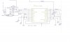
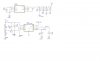
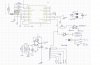
I made a rough sinewave with 10 digital steps added together. The steps caused pretty bad high frequency multiple harmonics which I filtered out with two 4th-order LMF40 switched-capacitor Butterworth lowpass filters in series. The filters had a small amount of clock frequency which I filtered out with a 2nd-order Sallen-Key lowpass filter made from an opamp.

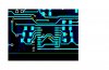
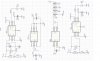
Here is a digital stepped sinewave with 20 steps (mine has 10 steps):
 

Attachments

  • 20-steps digital sinewave.png
    20-steps digital sinewave.png
    131.5 KB · Views: 229
Hey guys is it possible to use two of the max7410s to create a greater notch? In Cascaded fashion..
 
Last edited:
Okay so after having no luck with the maxim chips I went back to the lmf100. I etched a simple pcb for it and I switched the 555 IC to the cmos version.

I am not getting a real null though! I can tell there's a tiny null at 48hz(right around clk/1000) but its only a reduction of 200mV (417mV from 600mV)

Any ideas?
Do you really mean clk/1000, should be clk/100 ?

Edit: I did not notice, that the frequency of the notch depends on some resistor values.
 
Last edited:
Yeah
Do you really mean clk/1000, should be clk/100 ?

Edit: I did not notice, that the frequency of the notch depends on some resistor values.
yeah, in the example I'm using in the datasheet it is /1000. I will try and change this for different results later but I'm trying to see what's wrong first. I can look over my circuit for errors again but better yet I might aswell upload my pcb design here for you guys. Instead of being a program file it will be an image because it is pretty simple. I don't want to upload a schematic of it because the program I use, the sch looks strange/chaotic.
 
My LMF100 has a very deep notch when it was designed for the notch to be clk/100.
 
My LMF100 has a very deep notch when it was designed for the notch to be clk/100.

Yea but I must have another issue because getting only a 200mv attenuation from 600mV is almost nothing.

Eventually I am going to change it to be /100 but for now I just wanted to see at least a 40db notch...

I'd be willing to ship my circuit to someone if they have the time to take a look at it?
 
Last edited:
I am using MF10 N. same as lmf100.
I am using a ratio of 1 : 64 .
Around 5.6 Khz of square wave input clk i.e. around 88 or 89HZ of center frequency there is a 15mv to 20 mv sinewave at the output at both the channels while i/p signal is zero/grounded through 120k resisistor.
My square wave generator is providing 0-3v squarewave. I am using fig 45 mode 3 A according to datasheet ( https://www.ti.com/lit/ds/symlink/mf10-n.pdf ).
Any idea HOW TO GET RID OF THIS SINE WAVE at o/p?
Thanks.
 

Attachments

  • MF10N.JPG
    MF10N.JPG
    64.1 KB · Views: 146
  • SDS00003.BMP
    750.1 KB · Views: 141
  • SDS00002.BMP
    750.1 KB · Views: 142
  • SDS00001.BMP
    750.1 KB · Views: 148
Last edited:
How are the various grounds from the IC and clock source arranged?
Also, what decoupling arrangements do you have from the various power pins to ground?

If it's on a breadboard it may simply be ground noise or crosstalk between signal connections.
 
Thank you for replying.
I am providing you the decoupling arrangements.
It is on a PCB not in a bread board.
I do not think noise look like a single sinusoidal signal in a DSO.
It appears only at certain frequencies .As I said earlier It appears at 30 Hz (centrefrequency) 90Hz & 5.56Khz . Mostly the 9O Hz output is greater and clear than others. I have supplied 640Hz (10HZ center frequency) to 6400000Hz (10khz centre frequency) to clk input. Out noise appears only at the above mentioned 3 frequencies at both channels together.
The ground is connected to battery negative terminal. Vcc is 5 volts. Gnd is 0 volt i.e. battery negative teminal. Vee is -3.7 volts. signal (function) generator is supplying clk pulses from out side. the (function gen)ground is connected to battery negative terminal.
 

Attachments

  • pcblayout.JPG
    pcblayout.JPG
    99 KB · Views: 144
  • decoulpling.JPG
    decoulpling.JPG
    49.4 KB · Views: 151
Last edited:
There are no decoupling capacitors in that bit of the PCB layout and you have both analog and digital grounds cross connected then to something else through the same via.

The whole thing should really be either using ground plane construction or "star point" ground for all the analog signals, with digital ground separate and only connected to the analog side at a single point, to my way of thinking.

Without seeing the full board - all layers - the stray output could even be a side effect of the 7660 oscillator.
 
I attached the gerbers. You can check them if you want. It is a two layer PCB. Top copper is covered with ground.
I tried to attach two 22uf capacitors externally between VCC , Ground & VEE ,Ground. but nothing changed.
.Unfortunately I can not apply star ground for digital grounds for now . I applied star point ground only for the USB ground here. I also have a separate 5V supply for USB. Even though I am not using USB port the problem appears.
7660 output looks clean in the scope.
 

Attachments

  • 6060_V1_ANA.zip
    128.7 KB · Views: 137
  • other.JPG
    other.JPG
    251.9 KB · Views: 146
  • voltage supply.JPG
    voltage supply.JPG
    236.5 KB · Views: 149
Last edited:
Your schematics are a fuzzy JPG file type so I can't read the texts. If you saved them as a PNG file then they will be clear.
Are you using an old "general purpose" TL062 dual opamp? You are using it in the REF circuit trying to make its input and output at voltages that are not shown and might be impossible.
1) What voltage is Vref?
2) What voltage is Vcc?
3) Why are you causing it to oscillate by connecting a capacitor to ground at its output? If you remove that capacitor then its high noise level will be obvious.

A TL062 is a low power version of an old TL082 that has a problem called "opamp phase inversion" which causes its output to go as high as it can when an input voltage becomes within a few volts from its negative supply voltage (your ground voltage for it) which might be happening with your oscillating TL062.
'Scope its output to see if it is oscillating and/or if its output DC voltage is as high as it can go.
 
Thanks for your advice .I will try to change Tl062 observe the results again.
VCC=5v.VEE=-3.9. volt. vref=2.5 volt. gnd is 0 volt
 
I think the TL062 is fine with the -3.9V Vee. But it is noisy and has a low output current.
EVERY opamp you try will oscillate when it has your C37 shorting its output. Since the opamp has negative feedback then the phase shift caused by the capacitor will cause the feedback to be positive.
 
EVERY opamp you try will oscillate when it has your C37 shorting its output

The normal approach to driving a capacitor or capacitive load is simply to add a low value resistor between the opamp output pin and the cap / feedback point.

That should stabilise it without compromising the reference voltage.

Try eg. 47 or 100 ohms.
 
The problem was in the lmf 100 Ic. It was draining too much of negative supply. I changed the Ic and now the VEE supply increased to -4.36 volt . 7660 output was oscillating.
Thanks.
 
Status
Not open for further replies.

Latest threads

New Articles From Microcontroller Tips

Back
Top