Continue to Site

Welcome to our site!

Electro Tech is an online community (with over 170,000 members) who enjoy talking about and building electronic circuits, projects and gadgets. To participate you need to register. Registration is free. Click here to register now.

  • Welcome to our site! Electro Tech is an online community (with over 170,000 members) who enjoy talking about and building electronic circuits, projects and gadgets. To participate you need to register. Registration is free. Click here to register now.

lm7805 capacitors!!

Status
Not open for further replies.
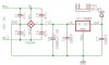
i am using 7805 regulator for getting 5v voltage...in its datasheet it says that we have to connect a capacitor between Vi and ground pin and another capacitor between Vo and ground pin...why are these capacitors required and can the regulator without these capacitors??
 
Yes it will regulate without the use of these caps, but not recommended. The Vi/Vo caps are used for filtering out RF signals and help your regulator have a cleaner output. Otherwise you could get spruious signals coming in, that won't get filtered and cause your 5V rail to be noisy. This could cause problems depending on what you are powering.
 
The capacitor improves the transient response.

When you connect and disconnect a large load - when the load is connected there's a voltage troff and then the load is disconnected there's a voltage spike. Adding a capacitor in parallel with improve the situation as it will provide power during thr troff and absorb the spike.

The input capacitor isn't required if the regulator is close (<150mm) to the battery or rectifier smoothing capacitor.

https://www.electro-tech-online.com/threads/12-22vdc-to-5vdc-converter.39190/
 
Last edited:
The input capacitor is recommended if the regulator is more than a couple of inches away from the filter in the DC power source. This capacitor helps get rid of noise "riding" on the DC input.

The output capacitor helps minimize transients and high frequency noise on the output from the regulator.

In non-critical applications, you can do without them. Also, the values are not very critical. 100 nF (0.1 F) in and out will be fine in most cases.
 
i have to convert 12v from a dc adaptor ..is it recommended to use capacitors??

Always use them. As the guys have said, they are used for filtering. Regulators can also be prone to oscillation if any noise is induced as well. Usually you only need to filter the output but it is good design practice to use both. I like about a 4.7uf cap on the output. .1uf should be sufficient on Vin.
 
Yes, use both input and output capacitors.
 
What kind of current are you drawing from the 7805? Anything more than about 175mA @ 12V, is going to start producing a lot of heat!

Jim
 
I recommend using 10-100uF capacitors on the input and the same on the output. It is a good practice to use a .1uf cap in parallel on both input and output. Electrolytics do not filter out high RF frequencies very well do to their design. The .1uf caps (i.e. ceramic or mica) do a much better job at higher frequencies. So use both.
 
Not only they filter RF, but also take care that the regulator won't oscillate.

You can fry any LM78XX type without any load connected just by oscillations.

It is always good practice to use four 47nF capacitors across each pin of a bridge rectifier.

The 100nF capacitors should be as close as possible connected to the regulator IC.

Check the screenshots for details.

Boncuk
 

Attachments

  • PWR-SUPPLY.jpg
    PWR-SUPPLY.jpg
    28.1 KB · Views: 3,606
  • SUPPLY-BOARD.jpg
    SUPPLY-BOARD.jpg
    34.1 KB · Views: 1,996
It is always good practice to use four 47nF capacitors across each pin of a bridge rectifier.
I've seen that before but I've never bothered using them.
 
Last edited:
I've seen that before but I've never bothered using them.

They are an advantage in an environment where machines are running, such industrial areas, reducing spikes and RF riding on the AC to a great extend.

Using pin spaces of double the pin space of the rectifier AC in and DC out can be straight lines on the PCB layout.

Hans
 
They are an advantage in an environment where machines are running, such industrial areas, reducing spikes and RF riding on the AC to a great extend.
I'm still not convinced.

The mains transformer will have a huge core loss at RF frequencies, therefore it should provide adequate suppression and a single 100nF ceramic capacitor on the output of the rectifier should remove any remaining RF.
 
Mains transformers will pass RF b/c of interwinding capacitance, so I think Boncuk is right. True isolation transformers take extra precautions to prevent this.
 
Last edited:
Small capacitors across rectifiers can reduce RF interference caused by diode switching. I see it mostly in receivers.
 
I agree with all sugestions.

One question though...

How about using bigger electrolitic caps ( ex. 1000uF )?
Not recommended or just overkill ?

.
 
Last edited:
I agree with all sugestions.

One question though...

How about using bigger electrolitic caps ( ex. 1000uF )?
Not recommended or just overkill ?

.

Not in this application. It would be over-kill since he is using an AC adapter outputing 12Vdc. There won't be that much ripple. The larger caps would be used if powering from an AC source, post-rectification.
 
I agree with all sugestions.

One question though...

How about using bigger electrolitic caps ( ex. 1000uF )?
Not recommended or just overkill ?

.

Hi ruijc,

using an electrolytic of 1,000µF per expected current flow of 1A is no overkill.
ICs tend to work most reliably with smooth DC for supply. :)
 
Hi ruijc,

using an electrolytic of 1,000µF per expected current flow of 1A is no overkill.
ICs tend to work most reliably with smooth DC for supply. :)

I certainly agree that ICs work best with smooth DC, but when he asks if they are over-kill, I think not necessary (over-kill). The AC adapter filters out most of the ripple anyway. A 100uF cap on the input and output is sufficient. But, ruijc, if you want to spend the extra money and real estate and use a larger cap, it won't hurt anything.:rolleyes:
 
Hi

sorry to dig up an old thread, but i just have a quick question and this is very relevent - I am building a relay box/power supply/square wave generator.

I plan on having 230v IEC mains plug on the back, through a fuse, transformer to 15v, bridge rectifier (with the filter caps earlier in the thread).

Now on to the question, I want to have a 7805 drawing 200mA, a 7805 capable of drawing 1A, and a 7812 capable of drawing 1A.

What size of capacitor would be suitable to use as the storage cap (the one that goes after the rectifier before the regulator. I have a few 2200uF and a few 4700uF. would any of these (or a combination) be suitable for this, if not what would?

The load on 1 of the 7805's and the 7812 may be switched on and off regularly.

I have all the smaller caps for use with the regulators.

Thanks
 
Status
Not open for further replies.

Latest threads

Back
Top