Electro Tech is an online community (with over 170,000 members) who enjoy talking about and building electronic circuits, projects and gadgets. To participate you need to register. Registration is free. Click here to register now.
Welcome to our site! Electro Tech is an online community (with over 170,000 members) who enjoy talking about and building electronic circuits, projects and gadgets. To participate you need to register. Registration is free. Click here to register now.
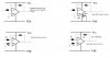
Your schematic does not show power supply voltages. Maybe it has no power supply.
An ordinary opamp cannot drive a load as low as only 320 ohms. Your feedback resistor values are much too low and become the load. Try 22k and 10k instead of 220 ohms and 100 ohms.
If you have both positive and negative power supplies connected to the +V and -V pins respectively, and if you connect the input pin to ground (not floating), then your output should be very close to zero volts. If you haven't done both of these things, the the output will not be zero volts.
i thought it is a known fact that only ideal op amps have the assumption that Vo=0V when Vi=0V. however, in real life, u often get a small amount of votlage (in mV or uV range) at the output before putting in any input...
Thats right.
There is a dc offset with practical opamps.
As mentioned above, without having a dual supply, and the input pin connected to ground (i.e not left open), the output will be CLOSE but not at 0V due to the dc offset.
haha at last i can post a useful answer! (i hope)
Funny enough i am reading about the 741 in my textbook at the moment, and am having a related problem with the 741.
There are several things that cause a non 0v output for a 0v input;
Input offset voltage
Input bias current
Input offset current
These effects may sum or partially cancel each other!
Input offset voltage is due to manafacturing variations causing non perfectly balanced input stages. The difference in input voltage you must supply to give 0v output is called input offset voltage.
For the 741 you connect a 10k pot between pins 1 and 5 with wiper connected to the -ve supply rail VEE
The input offset voltage will drift with temperature and time however.
Input bias current is half the sum of the input current with inputs tied together.
Input bias current is simply the base/gate current of the input transistors.
A 741 has bipolar juction transistors on input which draw a relativly high current compared to Jfet input op amps such as the 411
Input bias current causes a voltage drop across the feedback resistors.
To make its effects negligable you must ensure resistance of inputs to op amp match.
Input offset current is due to manafacturing variations resulting in non symmetrical input circuit. The result is even if u match source impedances for input bias current the voltage drop across the resitors will not be the same so the input sees a difference voltage which it amplifies to give non 0v output. The only 'remedy' to this error is to use resistors of moderate value as the larger the resistor the higher the voltage drop.
This site uses cookies to help personalise content, tailor your experience and to keep you logged in if you register.
By continuing to use this site, you are consenting to our use of cookies.

")