Electro Tech is an online community (with over 170,000 members) who enjoy talking about and building electronic circuits, projects and gadgets. To participate you need to register. Registration is free. Click here to register now.
Welcome to our site! Electro Tech is an online community (with over 170,000 members) who enjoy talking about and building electronic circuits, projects and gadgets. To participate you need to register. Registration is free. Click here to register now.
Hello!
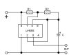
I need a circuit in which the frequency of LM555 astable multivibrator can be controlled externally I mean by the help of transistor etc. So, please guide what modification may be done in the attached circuit
I do not need a precise VCO, actually I want to control the frequency by the help of R2R (ladder network), where the digital input value will increase/decrease the DC voltage of R2R network, so the frequency may be varied from 1Hz to 5Khz (i.e. My desired frequency). So what should I do?
I do not need a precise VCO, actually I want to control the frequency by the help of R2R (ladder network), where the digital input value will increase/decrease the DC voltage of R2R network, so the frequency may be varied from 1Hz to 5Khz (i.e. My desired frequency). So what should I do?
I do not need a precise VCO, actually I want to control the frequency by the help of R2R (ladder network), where the digital input value will increase/decrease the DC voltage of R2R network, so the frequency may be varied from 1Hz to 5Khz (i.e. My desired frequency). So what should I do?
I misunderstood. Varying the frequency of a simple 555 astable by varying voltage doesn't work very well, but varying frequency by changing resistance in the timing network can work quite well.
If you are planning to use a R/2R ladder, how many different discrete frequencies would you like to get?
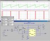
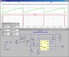
Also, it is possible to build a voltage-controlled current-source, which in turn drives the timing capacitor in the 555 astable, which does give a reasonable F vs V curve.
I attached a sim of the 555 driven from a current source. I played with the values to get 5KHz and about 5Hz as the control input goes from 0 to 8V. If you change the supply voltage, you will have to re-optimize the other resistor values. Temperature stability will not be very good.
Scroll down until you find fig. 10. It's a little complex, but it allows wide freq variation and maintains 50% duty cycle, or 1:1 mark/space as our British friends say
Scroll down until you find fig. 10. It's a little complex, but it allows wide freq variation and maintains 50% duty cycle, or 1:1 mark/space as our British friends say
Sorry, I was responding to the orginal post that said he wanted to use a transistor, etc., and wanted to modify the attached ckt.
EDIT: Getting back to fig. 10, it would be possible, I think, to replace the var. resistor with a FET biased in the linear region as a controlling device. I've often thought about that, but never tried it.
I do not need a precise VCO, actually I want to control the frequency by the help of R2R (ladder network), where the digital input value will increase/decrease the DC voltage of R2R network, so the frequency may be varied from 1Hz to 5Khz (i.e. My desired frequency). So what should I do?
I think you could do it easy enough with a 2 transistor multivibrator.
Since the "threshold" voltage is only 0.6v to trigger the base of the transistor(s) your incoming voltage from your R2R network would cause the base cap(s) to charge quicker and give you frequency control, which would be inverted.
It's not that elegant but then you don't need a precise VCO.
It is simpler than a 555+transistor etc and if you apply your control voltage to BOTH transistor bases of the multivibrator you should be able to maintain a decent 50:50 duty cycle while varying the frequency, although that may cost an extra couple of resistors.
This site uses cookies to help personalise content, tailor your experience and to keep you logged in if you register.
By continuing to use this site, you are consenting to our use of cookies.

")