Continue to Site

Welcome to our site!

Electro Tech is an online community (with over 170,000 members) who enjoy talking about and building electronic circuits, projects and gadgets. To participate you need to register. Registration is free. Click here to register now.

  • Welcome to our site! Electro Tech is an online community (with over 170,000 members) who enjoy talking about and building electronic circuits, projects and gadgets. To participate you need to register. Registration is free. Click here to register now.

LM393 design circuit

Status
Not open for further replies.

jayson042907

New Member
Hello!

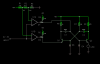
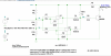
I have a problem with designing the LM393 differential comparator.

My application is when the LM393 comparator detects a voltage range of 3V to 4V, the LED will blink.
A voltage is higher than the 4V, the LED = ON. While a voltage lower than the 3V, the LED = OFF.

Can anyone help me how to design this kind of circuit?

Thank you!
 
Search for Window comparator circuit... You only need to detect two levels with two Op-Amps 3V and 4V. i.e. 3V and below do nothing. above 3V blink (use an oscillator circuit ... could be constructed from a Spare Op-Amp), above 4V steady ON .... (stop the oscillator in a HIGH condition or bypass the oscillator section using diodes in an "OR" configuration)
 
Search for Window comparator circuit... You only need to detect two levels with two Op-Amps 3V and 4V. i.e. 3V and below do nothing. above 3V blink (use an oscillator circuit ... could be constructed from a Spare Op-Amp), above 4V steady ON .... (stop the oscillator in a HIGH condition or bypass the oscillator section using diodes in an "OR" configuration)

Thank you for your reply. I really appreciate it.

Can I use the LM393 as a window comparator circuit? Do you sample diagram for this circuit?
I'm new in designing a circuit so, I don't have any idea how to start.
 
The LM393 IS a comparator, so making a "comparator window" simply uses two comparators with different voltage thresholds.

In the attached image D1 and D2 are only there for simulation purposes to simulate the open collector nature of the LM393.

R1,R2, and R3 form a reference voltage divider for the comparator window. The reference voltages are close to 3V and 4V using standard resistor values.

*R4 and R5 serve as pullup resistors for the open collector comparator output.

*R4, R6, R7, R8, C1, C2, Q1, Q2, D3, and D4 form a classic multivibrator (oscillator)

Note: *R4 serves a s a pullup resistor for the open collector comparator output as well as one of the resistor legs in the multivibrator.
Note: Circuit blinks the LED at about 2 flashes per second

The multivribrator is configured or "gated" in a way to adhere to the desired input logic requirements ....

1) less than 3V the LED is off
2) 3V to 4V the LED blinks
3) greater than 4V the LED is steady
 

Attachments

  • Homework.PNG
    Homework.PNG
    14.8 KB · Views: 337
Hello

Here's one that uses a self blinking LED.
Each comparator has about 50mv hysteresis.

eT
 

Attachments

  • winComp.png
    winComp.png
    141.1 KB · Views: 303
eTech ... how do you make the blinking LED steady ? ... the OP only wanted the LED to blink when the input voltage was between 3 and 4 and for the LED to be steady ON when the voltage was above 4V
 
eTech ... how do you make the blinking LED steady ? ... the OP only wanted the LED to blink when the input voltage was between 3 and 4 and for the LED to be steady ON when the voltage was above 4V

Hi

Yes....it will only blink between 3 and 4 volts.
However, the op didn’t state what you described either,
The required operation needs to be clarified.

eT
 
To get the three output states from two comparators you will need some added logic at the comparator outputs.
Why must it be an LM393 comparator?
Is this homework?
 
To get the three output states from two comparators you will need some added logic at the comparator outputs.
Why must it be an LM393 comparator?
Is this homework?

My guess is that this might be homework, this why I labeled the schematic "homework".

As far as logic, it can be obfuscated with the interaction of a couple of transistors in an existing circuit section ... see the multivibrator section of my proposed schematic solution.
 
As far as logic, it can be obfuscated with the interaction of a couple of transistors in an existing circuit section
Yes, I missed that.
Good design.
 
My guess is that this might be homework, this why I labeled the schematic "homework".

As far as logic, it can be obfuscated with the interaction of a couple of transistors in an existing circuit section ... see the multivibrator section of my proposed schematic solution.

Thank you very much for your help.

The real purpose of the project is for detecting the supply if:
a. low voltage (3.0V ~ 4.0V) - the LED start to flicker
b. shutdown voltage (below 3.0V) - the LED OFF
c. stable voltage ( greater 4.0V) - the LED ON.

I'm doing now the experiment but first I have a question:
a. Is it possible that the supply of the LM393 will be used as an input voltage?
It means that it will self detect it's own supply if already LOW.
 
Status
Not open for further replies.

Latest threads

New Articles From Microcontroller Tips

Back
Top