Continue to Site

Welcome to our site!

Electro Tech is an online community (with over 170,000 members) who enjoy talking about and building electronic circuits, projects and gadgets. To participate you need to register. Registration is free. Click here to register now.

  • Welcome to our site! Electro Tech is an online community (with over 170,000 members) who enjoy talking about and building electronic circuits, projects and gadgets. To participate you need to register. Registration is free. Click here to register now.

LM3915 won't display in bar mode

Status
Not open for further replies.
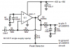
I made an extended range VU meter like in the LM3915 data sheet (the exact same one) the only difference is that the pot is a 20k pot. The "upper" VU chip won't display in bar mode, only dot mode even though pin 9 is connected to V+

Why can't I get it to change? I know it's not the chip because I tried with 3 different VU meters and they all worked in bar mode for the lower segment but they all displayed in dot mode for the upper portion.
 
May I suggest you check the following;

Application Hints
The most difficult problem occurs when large LED currents
are being drawn, especially in bar graph mode. These currents
flowing out of the ground pin cause voltage drops in
external wiring, and thus errors and oscillations. Bringing the
return wires from signal sources, reference ground and bottom
of the resistor string to a single point very near pin 2 is
the best solution.
Long wires from VLED to LED anode common can cause
oscillations. Depending on the severity of the problem
0.05 μF to 2.2 μF decoupling capacitors from LED anode
common to pin 2 will damp the circuit. If LED anode line
wiring is inaccessible, often similar decoupling from pin 1 to
pin 2 will be sufficient.
If LED turn ON seems slow (bar mode) or several LEDs light
(dot mode), oscillation or excessive noise is usually the
problem. In cases where proper wiring and bypassing fail to
stop oscillations, V+ voltage at pin 3 is usually below suggested
limits. Expanded scale meter applications may have
one or both ends of the internal voltage divider terminated at
relatively high value resistors. These high-impedance ends
should be bypassed to pin 2 with at least a 0.001 μF capacitor,
or up to 0.1 μF in noisy environments.
 
I currently have a 220uF filter capacitor connected to V+ supply of the circuit but it is still drawing a lot of current because it is messing with the actual radio. Would adding the 2.2uF cap to the common of the LEDs really make that much of a difference? Each LED has a 100 ohm resistor connected to the anode of each LED before they are connected to the voltage supply. I was also trying to get the circuit to display in dot mode but have all of the LEDs in series to improve efficency. I calculated that it would take 45V to drive all of the LEDs, but what if I cut the total number in half and connect all of the LEDs for a single VU chip in series? That would get rid of the huge current draw from the circuit, and it would also eliminate the problem of trying to display in bar mode because it would display automaticly.

Also; I have an LM386 acting as a buffer amp because the signal from the speaker is just too small to drive the peak detector (I switched from the 2.7 ohm speakers to 8 ohm speakers). The problem is that the buffer amp is much more sensitve to signal from the output of the actual amp. Is there a way that I can make the buffer amp drive the VU meter without causing clipping (which is the current problem) with out the huge complicated circuit that I came up with? I can give you the circuit diagram but I will need time to complete it.
 
Why do you have a resistor connected in series with each LED? If the supply voltage for the LEDs is too high and causes the LM3915 to heat too much then only a single power resistor can feed all the LEDs and will share the heat.

Why don't you use a simple single-supply opamp as the peak detector like I did? It can have any amount of gain to avoid clipping.
 

Attachments

  • peak detector.PNG
    peak detector.PNG
    16.2 KB · Views: 1,000
I had a resistor on the common of each LED because when I used a single power resistor, all of the LEDs started to dim noticeably. It was an attempt to avoid that problem which worked a little bit (they didn't dim as much).

My peak detector is a simple one that uses just a diode on the anode of a 22uF capacitor, and a 10k resistor to ground. All of which fed into the pin 5 of the 3915. The problem that I'm having with the buffer amp is that when the volume is lower, the signal needs to be increased (it functions normally with the inputs connected to the respective leads of the speaker). However when the volume gets turned up on the radio, a resistor needs to be added to between the inverting and non-inverting inputs on the buffer amp.

It's a problem that I've been trying to fix by tracing the signal back to the input of the amp, except that the volume is controlled by connecting a linear pot to the input, which makes it harder to trace it back. I connected the buffer amp to where the signal input should originate from but all I got was a bunch of static from the amp. I'm going to try again to see if removing a few parts will help to alleviate the situation.

In the 2 schematics that I've posted are of the circuits that I'm using. The first is of the peak detector and the buffer amp, the second one is of the circuit that I was going to try to use to control the gain of the buffer amp (may need to add more diodes to the positive feedback to allow the voltage to drop more rapidly). The LM741 is going to be replaced with an ICL7611.
 

Attachments

  • LM3915 amp, peak.JPG
    LM3915 amp, peak.JPG
    41.9 KB · Views: 620
  • 3915 gain control.JPG
    3915 gain control.JPG
    26.5 KB · Views: 574
The outputs of an LM3915 have regulated currents so if the single series resistor was calculated correctly then the LEDs will not dim.

You never short together the inputs of an opamp to reduce the gain. You simply add more negative feedback by bypassing the feedback resistor. A single transistor or Jfet can do it if you use a single-supply opamp.
A lousy old 741 opamp is not a single supply opamp and will not work in your circuit.

Your odd circuit creates many questions:
 

Attachments

  • LM3915 circuit.PNG
    LM3915 circuit.PNG
    76.7 KB · Views: 799
Last edited:
To start, the bypass capacitor for the supply is 220uF and is used by all of the ICs in the circuit not just the 386. According to the PCB, the speaker is connected to ground, but for some reason my ohm meter reads that there is a 10 ohm drop some where in the circuit (without power and without the speaker attached. The missing RC network was a mistake that I made when I originally built the circuit, but once I added it, it didn't seem to make any difference in performance so I just left it out to save some parts. The 4.7 ohm resistor needs to be such a low value because if I go any higher, the transistor on the other side of the isolator will not respond to the signal. The opto-isolator is included because of a trade off that I made in the design; if I use a single 3915, then the signal will cause it exceed the reference and all of the LEDs stay on most of the time. However, if I used 2 LM3915 ICs, then the signal would only light half of the second IC which is not what I wanted.

The 741 was just a cheap IC that I decided to use for the experimenting portion of this circuit. Like I said yesterday, It is going to be replaced with an ICL7611, 1.4MHz op-amp. I don't have access to any single supply op-amps, but when I get my charge pumps in a few days, I can make a dual supply.

But now I'm still left with 3 questions;
1.) You say that I shouldn't connect the inverting input directly to the output of the op-amp, why not? In this text book that I have in front of me, they have it configured in a similar mater so I saw no harm in doing so myself.
2.) If I do use a single supply op-amp, wouldn't such a configuration cause the output to oscillate because it is constantly dipping lower and higher than the reference?
3.) You said that there is an equation for calculating the resistor value for the LEDs, what is it? I've been through the entire data sheet 3 times and haven't found it

(Also, could the LM3915 be powered by +/- 10V referenced to ground and just have the input and on the other end of the internal resistor connected to ground?) I am trying to get the LEDs in dot mode to be supplied with the necessary voltage
 
The missing RC network was a mistake that I made when I originally built the circuit, but once I added it, it didn't seem to make any difference in performance so I just left it out to save some parts.
The datasheet for the LM386 power amp shows the important RC network in evey single schematic because the IC oscillates at a high frequency without it.

The 4.7 ohm resistor needs to be such a low value because if I go any higher, the transistor on the other side of the isolator will not respond to the signal. The opto-isolator is included because of a trade off that I made in the design; if I use a single 3915, then the signal will cause it exceed the reference and all of the LEDs stay on most of the time.
Your opto-isolator needs a very high input current for a small output voltage. You set the reference voltage of the LM3915 too low at only 1.25V. Your opto circuit simply attenuates the input signal because it has many voltage losses. If you set the reference voltage higher then the opto is not needed.
You have the reference voltage of the LM3915 adjusted to only 1.25V instead of a higher voltage (by using two resistors).

The 741 was just a cheap IC that I decided to use for the experimenting portion of this circuit.
The 741 opamp is 42 years old. Many much better modern opamps perform much better and cost the same or less.

I don't have access to any single supply op-amps
All modern countries have many distributors selling modern opamps. Do you live on Mars??

1.) You say that I shouldn't connect the inverting input directly to the output of the op-amp, why not?
Because it makes the voltage gain only 1 like a piece of wire.

2.) If I do use a single supply op-amp, wouldn't such a configuration cause the output to oscillate because it is constantly dipping lower and higher than the reference?
No.
The output voltage is simply the input voltage times the amount of voltage gain in the circuit.

3.) You said that there is an equation for calculating the resistor value for the LEDs, what is it? I've been through the entire data sheet 3 times and haven't found it
It is called Ohm's Law. The resistor value is the voltage across the current-limiting resistor divided by the current that you want. The voltage across the resistor is simply the supply voltage minus the LED voltage.

Also, could the LM3915 be powered by +/- 10V referenced to ground and just have the input and on the other end of the internal resistor connected to ground?) I am trying to get the LEDs in dot mode to be supplied with the necessary voltage
The LM3915 does not need a negative supply voltage. When its input voltage goes positive then it shows it.
When the input voltage goes negative then it ignors it.
When the Mode pin 9 is not connected then it is in the DOT mode.
 
Status
Not open for further replies.

Latest threads

New Articles From Microcontroller Tips

Back
Top