Continue to Site

Welcome to our site!

Electro Tech is an online community (with over 170,000 members) who enjoy talking about and building electronic circuits, projects and gadgets. To participate you need to register. Registration is free. Click here to register now.

  • Welcome to our site! Electro Tech is an online community (with over 170,000 members) who enjoy talking about and building electronic circuits, projects and gadgets. To participate you need to register. Registration is free. Click here to register now.

LM3915 not working

Status
Not open for further replies.
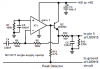
I was helping one of my friends build a VU meter using an LM3915, and it didn't work. I don't know what went wrong (I even built the circuit myself and it still didn't work). I think that we may have destroyed the chip so we plan on replacing it with a new one. This is the circuit that we made:**broken link removed**

The voltage supply was a PSU that had an output of 15V DC, and a current supply of 12A max. Our input was a function generator. We had an 8.2Ω resistor to simulate the speaker load.

We can't seem to figure out what went wrong, if someone could shed some light on the issue it would be appreciated.
 
hi DT,
What colour are the LED's also did you use the 15V supply to power the LED's.??

EDIT:
Did you keep the Mode pin o/c for DOT mode or did you connect the Mode pin to +v..??
 
Last edited:
The power supply was supplying the IC, and the LED's. The LEDs are 4 green, 3 yellow, 3 red. The green LEDs were 0.2 to 1.6W, followed by yellow and red respectively.

We tried the 3915 in both dot and bar mode. A friend took the chip out and pluged it in backwards, which is why I think that it has been destroyed (we don't usually let him touch expensive stuff like that)

Hi,
The LM3915 is set with that 390R to enable about 35mA thru each diode, if you use BAR mode you could fry the LM3915 as it will be dissipating well over 1.3Watts!!!

Whats the current rating of the LED's?
 
I don't know, the LEDs are from an unmarked package from Radio Shack.

hi,
I would limit the LED current to about 20mA/LED, so change the 390R to a 1k2 and the 2k7 to a 8k2 and use DOT mode.

If you want to use BAR mode insert a 39R 2.5Watt resistor between the +15v and the common of the LED Anodes.

This image is for a LM3914 but it shows the changes.

AAesp13.gif
 
How much can I vary the voltage with these settings?

Also, I tried to download your 3915 simulator and I was unsuccessful. How do I download it?
 
How much can I vary the voltage with these settings?

Also, I tried to download your 3915 simulator and I was unsuccessful. How do I download it?

hi,
I just did a test download of the LM3914 calc, no problems.
Just left click it and it should download to your PC, change the extension from .txt to .exe
As it says you need the free VB runtime files from the web
 
Most ICs are destroyed when plugged in backwards.

Your simple circuit does not have a peak detector circuit so its LEDs will be a dim blur.
 
Simply look at the three peak detector circuits in the datasheet.

I use this one on my Sound Level Indicator project. It uses a single-supply opamp so that a dual-polarity supply is not needed. It will work fine from the 14V of your car.
 

Attachments

  • peak detector.PNG
    peak detector.PNG
    16.2 KB · Views: 437
Status
Not open for further replies.

Latest threads

New Articles From Microcontroller Tips

Back
Top