Continue to Site

Welcome to our site!

Electro Tech is an online community (with over 170,000 members) who enjoy talking about and building electronic circuits, projects and gadgets. To participate you need to register. Registration is free. Click here to register now.

  • Welcome to our site! Electro Tech is an online community (with over 170,000 members) who enjoy talking about and building electronic circuits, projects and gadgets. To participate you need to register. Registration is free. Click here to register now.

LM3914 Voltmeter

Status
Not open for further replies.

goaticus

New Member
Now that my LED bar fuel gauge is functional, I would like to have the same type output for my bikes voltage level. I have built and tested the one below, but am bothered by it.

**broken link removed**

The author says
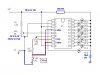
The first adjustment is to obtain 1.2 volts between U1's pins 7 & 4. I'm trying to remember why, but it has something to do with the LM3914's scaling or something. Do this by applying 12 volts (or so) to the circuit and adjusting VR2 until the 1.2 volt level is read.

However, adjustment of the pot does not affect the voltage reading above that is alread at 1,25V. I (with little to no knowledge) feel as though this circuit is possibly over complicated. Ideas...suggestions. 10.5 to 15V is a good range. TIA
 
hi,
Set it up like this image.
Between pins 7 & 8 is the 1.25Vref
 

Attachments

  • 1894-Voltmeterschematic.jpg
    1894-Voltmeterschematic.jpg
    34.4 KB · Views: 8,691
I did notice the voltages in the image. I appologize for my ignorance, though, as they do not answer my questions above. Does VR2 change the voltage of pin7 to 6.2V?
 
I did notice the voltages in the image. I appologize for my ignorance, though, as they do not answer my questions above. Does VR2 change the voltage of pin7 to 6.2V?
hi,
Consider when:
#1. VR3 is set to 0R and VR2 is set to 0R, the current thru the LED's will 11.5mA.
[Pin 7 will be 1.25V and pin 8 at 0v]

#2. VR3 is set to 0R and VR2 is set to 200R, the current thru the LED's will 9.9mA.
[Pin 7 will be 1.25V and pin 8 at 0v]

#3. VR3 is set to 5KR and VR2 is set to 0R, the current thru the LED's will 16.7mA.
[Pin 7 will be 6.48V and pin 8 at 5.23v], NOTE: still a 1.25V difference between pins 7 and 8

#4. VR3 is set to 5KR and VR2 is set to 200R, the current thru the LED's will 14.4mA.
[Pin 7 will be 5.71V and pin 8 at 4.46v], NOTE: still a 1.25V difference between pins 7 and 8

In your circuit as pin8 is linked to pin4, this means that LED#1 will light when the voltage on pin5
becomes ~4.46V and led#10 will light when pin5 voltage is ~5.71V.

So looking at the above 4 conditions, LED#1 will light when the voltage on pin5 approx equals that on pin 4
and LED#10 will light when the voltage on pin5 approx equals that on pin6

VR2 and VR3 do interact with each other as you adjust them.

NOTE: the markings on the LED's from 10.5v thru 15v are the attenuated battery voltage levels, the actual scale is ONLY 1.25V, so each LED lights on a 1.25v/10 = 0.125V increment.

When set up, the circuit should indicate your battery voltage from 10.5V thru 15V.
The 39R 1Watt resistor is important if you dont want to fry your LED's.:)
 
Thank you very much, Eric. This helps a lot. In tinkering with it last night, it seemed to only work properly with the VR2 Pot set to have the minimum (almost none; .6R) resistance between pins 6 and 7. If I am learning anything; am I correct in assuming I could replace VR2 with a 200R to pin 7 and connect pin 6 between the new 200R and R2 to make a fixed voltage divider...?
 
Wait... that doesn't sound right either. But, when I tried it with pins 6 & 7 connected and R2 going to 6 & 7, it didn't work... :confused: My issue is that if the pot is maxed one way or another, why not ditch it for a fixed resistor?
 
Wait... that doesn't sound right either. But, when I tried it with pins 6 & 7 connected and R2 going to 6 & 7, it didn't work... :confused: My issue is that if the pot is maxed one way or another, why not ditch it for a fixed resistor?

hi,
Normally pins 7 and 8 would be connected to each other thru a 1K resistor.
Pins 6 and 7 would be linked together.
When VR3 is half way [ 2k5], the voltage on pin 8 would be = 3.14V and pin7= 4.39v [ thats 1.25V across the 1K]
Pin 4 is connected to pin 8, so pin 4 is also at 3.14v
This means that you will have 1.25V from pin6 to pin4. [thats the scale]

So you will have to adjust VR1 , to give 3.14V when the Battery is 10.5V and 4.39V when the Battery is 15V.

It should work ok, where did you get the circuit from.???
 
A quick question on the LM3914 in this application. Could I ditch the resistor going to the LED's if I was only supplying the LED's with +8V? I ask because this Voltmeter is going to share board space with my other project, the Fuel Gauge which runs off of +8V. I have serious space issues with this project and the less components the better.
 
A quick question on the LM3914 in this application. Could I ditch the resistor going to the LED's if I was only supplying the LED's with +8V? I ask because this Voltmeter is going to share board space with my other project, the Fuel Gauge which runs off of +8V. I have serious space issues with this project and the less components the better.

hi,
Which circuit are you asking about.?
If its the one we have been working on, providing the individual LED currents are 15mA or less, when driving a BAR display, then +8Vled will be OK without the series resistor.
 
Eric, you were kink enough to help me with both. My question was referencing this 10.5-15V voltmeter circuit. I plan on running the voltmeter in floating point mode instead bar mode.
 
Last edited:
Eric, you were kink enough to help me with both. My question was referencing this 10.5-15V voltmeter circuit. I plan on running the voltmeter in floating point mode instead bar mode.
hi,
Omitting that resistor will not be a problem in DOT mode.
 
LM3914 Voltmeter corrections

First step calibration: IC Pins 4 & 6 are where you calibrate
for a voltage of 1.200 using VR2, Set your lab supply to 12
~ 13 volts and adjust VR2 for 1.200 volts, set & forget. 2nd
step calibration: With the power off adjust VR1 & VR3
trimpots to their center positions (2500 ohms). Final
calibration: Adjusting the SPAN trimpot VR1. Span voltage
is the difference between the highest and lowest LED
voltage reading, 15.00 vdc minus 10.50 = 4.50. Set your lab
supply to 12 ~ 14 VDC and adjust VR1 for a span voltage
of 4.50 VDC. It doesn't matter for now if the leds light at
the wrong voltage you are only adjusting to get the span
set to 4.50 volts.
Offset trimpot VR3 calibration: adjust your lab supply to
exactly 13.00 volts, adjust offset trimpot VR3 so led L6
(13 volt led) just turns on. Final test, vary the voltage on
your lab supply and check to see if all your leds light up at
the proper voltage.
Note: if you look at the National LM3914 datasheet it tells
you how to calibrate VR2 for 1.200 VDC.
I have built over a hundred car alternator/battery monitors
similar to this Solorb website project and they have been
working in 12 volt cars for a number of years. My circuit
design is the same except for the following changes:
it uses a voltage monitoring range of 11.5 ~ 15.6 and IC
pins 11 and 9 are connected together.
Led colors:
Led 1, 2, 9, 10 red.
Led 3 & 8 yellow
Led 4,5,6,7 green
 
Last edited:
The 39R 1Watt resistor is important if you dont want to fry your LED's.:)
No.
The LM3914 regulates the current to the LEDs. But since the 12V supply is much higher than the 1.8V to 3.5V for each LED then the LM3914 becomes overheated if the resistor is not there to share the extra voltage (which with the current causes heat).
 
No.
The LM3914 regulates the current to the LEDs. But since the 12V supply is much higher than the 1.8V to 3.5V for each LED then the LM3914 becomes overheated if the resistor is not there to share the extra voltage (which with the current causes heat).

If the LM3914 is on dot mode. do you still need the resistor or is it only for bar mode. I'm asking this because i build the same diagram on dot mode and my lm3914 didn't get hot
 
In the DOT mode only one LED is lighted. But in the BAR mode up to 10 LEDs are lighted so the heating of the IC is up to 10 times as much.
 
No.
The LM3914 regulates the current to the LEDs. But since the 12V supply is much higher than the 1.8V to 3.5V for each LED then the LM3914 becomes overheated if the resistor is not there to share the extra voltage (which with the current causes heat).

Again, you are taking parts of my posts out of context, I can only assume you are not reading thru the posts in the thread to see how its developing
or you are just trying to be a smart arxx...

One thing you should get clear when you start rattling my cage you are not dealing with some unfortunate Asian youngster who won't answer back.

For some unknown reason you seem to take pleasure in trying to confound OP's with ambiguous information instead of directly helping them with their projects.


This resistor will be required as the OP, was originally planning BAR mode.
However, adjustment of the pot does not affect the voltage reading above that is alread at 1,25V. I (with little to no knowledge) feel as though this circuit is possibly over complicated. Ideas...suggestions. 10.5 to 15V is a good range. TIA
 
Status
Not open for further replies.

Latest threads

New Articles From Microcontroller Tips

Back
Top